sales@hxdcircuits.com
+86 180 1876 7219

PCB Certifications

HXD’s Advantages in LED PCB Solutions

HXD is experienced with LED PCB fabrication,we are experts in thermal performance, structure stability and surface treatment. Our LED PCBs are used in automotive lighting, plant grow light projects, delivering stable electrical performance and reliable service life in real applications.
We support your prototype demands and mass production, and our experienced engineering team can support design improvement during the prototype stage.

led-pcb-copper

Dielectric Layer control capacity

During fabrication of metal core LED PCBs, the dielectric layer determines directly the thermal resistance performance of PCB. HXD can stably achieve a dielectric layer of ≤75μm,effectively reducing thermal resistance between the copper traces and the metal substrate.This enables faster heat conduction and lower LED junction temperature.

Copper Foil Treatment Process

To avoid issues like copper foil lifting and delamination in high-power LEDs under repeated thermal cycling,HXD’s optimized lamination process with high-adhesive copper foil enhances significantly the bond strength between copper foil and the dielectric layer, it can meet stable demands of applications like street lights,industrial/mining lights, and automotive.

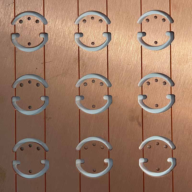
High Reflectivity Solder Mask Process

HXD offers white and matte white solder mask,it can effectively improve light reflectivity and reduce optical loss.

HXD LED PCB Detailed Design Flow

Parameter Setting

Before starting Led PCB layout and wiring, our engineering team will confirm all the key design parameters:

  • LED driver type: according to the actual demand to choose constant current (CC) or constant voltage (CV)
  • Power supply specification: Define the input voltage range and operating current to avoid overloading.
  • PCB size: customized design with the structure and installation space of LED lamps and lanterns
  • Trace spacing and minimum line width: to ensure safe insulation and solderability
1

Component Placement

  • Driver Protection Design: Integrated constant current driver chip or current limiting resistor, effectively preventing the current surge impact LEDs.
  • Layout principle:
    • LEDs must be arranged in regular arrays to facilitate automated welding and enhance heat dissipation uniformity.
    • High-frequency components and power supply alignment to maintain a reasonable distance to avoid the risk of EMI interference.
    • Enough safe distance between the pad and the alignment to improve the welding yield.
2

Substrate Material Selection

Substrate material directly determines the thermal performance and service life of the LED PCB, which is critical in customized design:

  • MCPCB: It is the most common solution. It consists of an aluminum base, a high thermal conductivity insulation layer, and a copper circuit layer. It is used for medium to high power LED lighting.;
  • FR-4 Substrate: It is only used for low-power indicator lights.For lighting, a large number of thermal vias must be designed to conduct heat to the copper foil on the backside.
  • Ceramic Substrates: For applications requiring high temperature resistance and reliability, such as medical and aerospace applications.
3

Routing

    • Current Carrying Calculation: Accurately calculate the line width according to the actual working current to avoid overheating.
    • Routing principles:
      • Prioritize power and ground lines to ensure stable power supply.
      • Ensure that the positive and negative poles of each LED are correctly connected.
      • Minimize cross wires and sharp corners to reduce electrical risks.


4

Design Rule Check

  • We will check the trace width, spacing, vias and pad sizes to avoid potential short circuit or fabrication risk.
  • Comprehensively verify the LED positive and negative connections and grounding design to ensure the circuit logic is correct and working stably.
  • We usually use White Solder Mask to enhance the light reflection rate, thus improving the overall luminous efficiency of LED PCBs.
5

Testing & Optimization

Finally, we will power on the PCB prototype for testing, focusing on LED light uniformity and circuit integrity

6

REQUEST A QUOTE

Supported file formats: PDF, DOC, DOCX, TXT, JPG, PNG (Max 2MB)