sales@hxdcircuits.com
+86 180 1876 7219

Metal Core PCB (MCPCB)

  • No MOQ
  • Aluminum PCB up to 6L
  • Copper PCB up to 4L with True Thermal–Electric Separation
  • Depth Milling,Counterbore/Countersink(Bell-shaped for better connector fit)
  • Fastest Lead time for Copper core is 10days
  • Stable Performance for High-Power LED & Power Electronics
  • Superior Heat Dissipation for Automotive & Industrial Modules

HXD METAL CORE PCBs

1Layer Aluminum PCB+PI

1Layer Aluminum PCB+PI

Aluminum + PI Hybrid Structure Combines high thermal conductivity with flexible PI, enabling creative designs and flexible interconnections not possible with standard MCPCBs.

1Layer Copper based PCB with Pillar Technology

1Layer Copper based PCB with Pillar Technology

Copper Core for Extreme Heat Dissipation Designed for high-power lighting applications, offering exceptional thermal conductivity up to 400 W/m·K, far beyond standard aluminum MCPCBs.

2Layer Aluminum PCB

2Layer Aluminum PCB

Offers improved routing flexibility and electrical performance compared to standard single-layer MCPCBs—ideal for more complex lighting designs.

What is MCPCB?

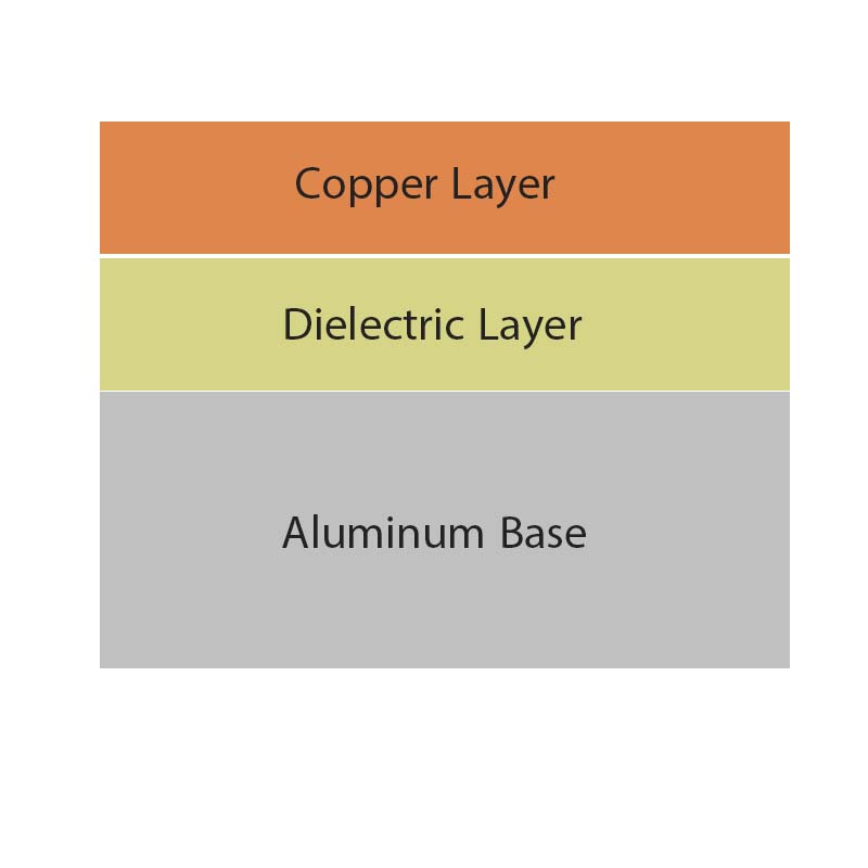
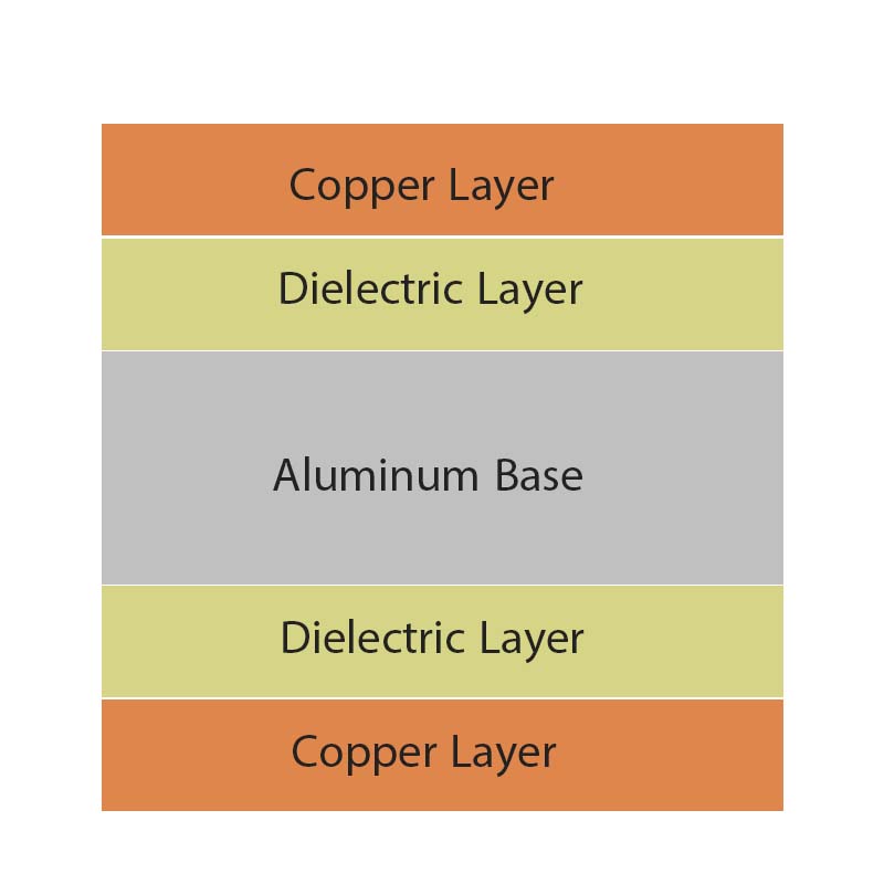
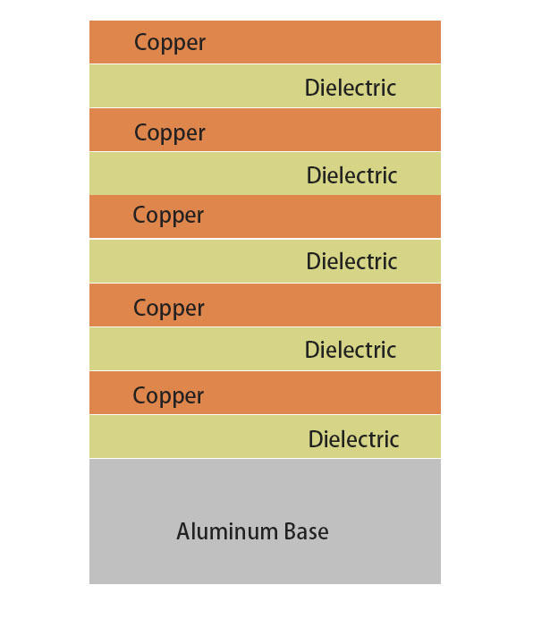
Metal Core Printed Circuit Board (MCPCB), also referred to as Insulated Metal Substrate (IMS) PCB or Thermal PCB, is a specialized type of PCB that differs from traditional FR4 boards by incorporating a metal base to enhance heat dissipation. During operation, electronic components generate heat, and the metal core efficiently channels this heat away from critical areas to less sensitive regions, such as metal heat sinks or the core itself.

The most commonly used metals for MCPCB cores are aluminum, copper, and steel alloys:

  • Aluminum provides excellent thermal conductivity and heat dissipation while remaining cost-effective, making it the preferred choice for standard MCPCBs.

  • Copper offers superior performance in heat transfer but comes at a higher cost.

  • Steel, including both regular and stainless steel, is mechanically stronger than aluminum and copper but has lower thermal conductivity.

The selection of core material depends on the specific application, taking into account thermal performance, mechanical rigidity, and cost. Considering these factors, aluminum emerges as the most practical and economical option for most MCPCB designs.

METAL CORE PCB APPLICATIONS

High-power PCBs naturally generate a lot of heat. When your board needs to cool down quickly, a Metal Core PCB is usually a much better choice than standard FR4.Here are some of the most common applications where this type of technology really shines:

  • Photovoltaics
  • Telecom & Industrial
  • Automotive Electronics
  • Power Supplies
  • Power Conversion Systems
  • LED Lighting

METAL CORE PCB TECHNOLOGY BENEFITS

When an application needs strong heat dissipation, Insulated Metal Substrate (IMS) technology brings a lot of real advantages.That’s why many engineers and designers choose Metal Core PCBs—they can get the following benefits that regular FR4 boards just can’t match:

  • Superior heat dissipation
  • Great durability of Aluminum
  • Eliminate heat sinks and other voluminous hardware
  • Lightweight and strength

SINGLE LAYER

Single Layer MCPCB (Metal Core Printed Circuit Board) is the simplest and most commonly used type of metal-based PCB. It consists of a single copper conductive layer on top, a
metal base plate (e.g. Aluminum) to provide rigidness to
the circuit board and a thermal conductive dielectric
working as the insulator.

Send Your Inquiry Now

DOUBLE SIDED

A Double Layer MCPCB (Metal Core Printed Circuit Board) is a type of metal-based PCB that features two conductive copper layers separated by a dielectric insulation layer, all built on a metal core substrate such as aluminum, copper, or steel alloy.

Compared to a Single Layer MCPCB, the double-layer design provides more routing space, higher circuit density, and better electrical performance, while still maintaining excellent thermal conductivity thanks to the metal base.

Manufacturing Challenges:

Lamination Technology: Ensuring strong adhesion between the copper layers on both sides and the aluminum base to avoid delamination.

Insulation Treatment: The dielectric layer must maintain high insulation resistance (typically withstand voltage ≥ 2 kV).

Drilling & Hole Metallization: After drilling on the aluminum base, special treatments (such as plating the hole) are required to achieve electrical connection between the two sides.

Send Your Inquiry Now

MULTI LAYER

A multi-layer MCPCB consists of two or more conductive layers separated by the thermally conductive dielectric material. At the bottom of the structure is the metal substrate, and SMT components can only be placed on one side. The use of THT components is not allowed, but it provides the possibility of manufacturing blind vias and buried vias with internal signal layers and power or ground planes.

Compared to regular FR4 material, this structure requires more technical expertise and experience to laminate the multiple layers of traces with the metal core. Additionally, the cost is much higher than that of a two-layer MCPCB or a double-sided metal-based PCB.

Send Your Inquiry Now

Get started with Metal Core PCBs

We can turn your standard technology PCBs in as fast as in 48 hours.
Start Custom Quote

REQUEST A QUOTE

Supported file formats: PDF, DOC, DOCX, TXT, JPG, PNG (Max 2MB)