sales@hxdcircuits.com
+86 180 1876 7219

Rigid Flex PCB-Reliable Quality with Competitive Cost

  • No MOQ
  • DFME Professional Engineering to give suggestion to smooth the production
  • Fastest Lead Time for Samples in 10 Days
  • HDI & Up to 20 Layers
  • Min. Line width/spacing 3/3mil
Get a quote

What is Rigid-Flex PCB?

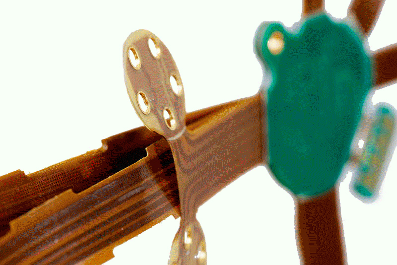
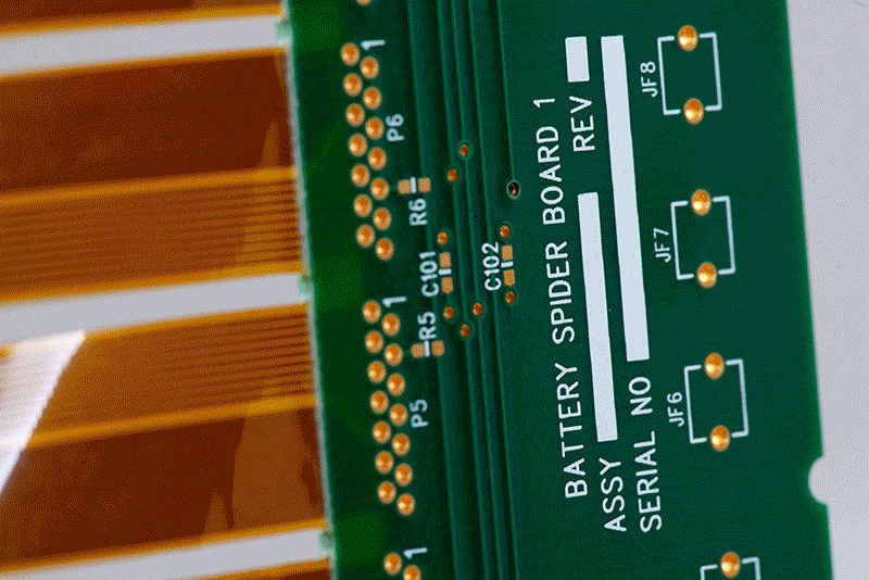
A Rigid-Flex circuit board (RFPCB) is a special type of PCB that combine the Rigid PCB and flex PCB through a lamination process. It doesn’t need additional connectors or solder joints. By this way, it can provid greater design freedom for complex electronic systems.

Rigid-Flex PCBs are widely used in applications with strict requirements for reliability, space utilization, and weight reduction. It’s always applied in some high requirement industries, such as drones and medical equipment.

Advantages of Rigid-Flex PCBs over standard PCBs:

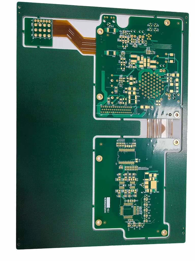
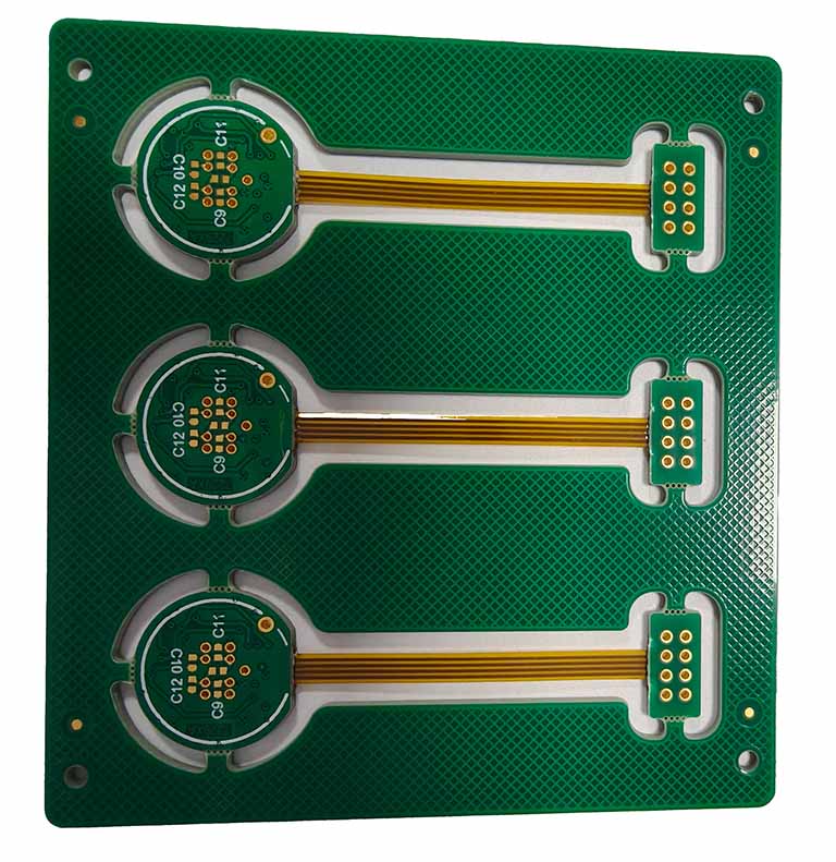
1.Integrated design: The rigid and flexible sections are tightly integrated. It can eliminate the need for additional connectors or wiring harnesses.
2.Adaptability to complex spaces: The flexible part can be folded or bent in three dimensions, saving space.
3.High reliability: Due to the reduction of solder joints, cables, and connectors, the risk of system failure is significantly reduced. Especially it is better in environments with vibration, shock, and temperature changes.
4.Excellent electrical performance: Shorter signal paths reduce impedance discontinuities and signal loss. It can improve signal integrity.

Although the cost of rigid-flex PCBs may be higher than standard FR4 PCB or Flex PCB. Considering their overall advantages, they are often a more cost-effective solution.

PCB Certifications

HXD’s Rigid-Flex PCBs

10 layer HDI Rigid-flex PCB

10 layer HDI Rigid-flex PCB

Advanced 10-Layer Rigid-Flex Stackup (FR4 + PI) Supports compact medical equipment designs while ensuring long-term bending reliability.

2L Rigid-flex PCB

2L Rigid-flex PCB

Rigid-Flex Stackup (FR4 + PI) Combines durability and flexibility, enabling compact designs and dynamic bending for communication devices.

4Layer Rigid-flex PCB

4Layer Rigid-flex PCB

Stable 4-Layer Rigid-Flex Design (FR4 + PI) Combines flexibility and rigidity to support compact layouts and dynamic bending in industrial control applications.

8Layer Rigid-flex PCB with Dupont AP8535R and Arlon 49N

8Layer Rigid-flex PCB with Dupont AP8535R and Arlon 49N

Advanced 8-Layer Rigid-Flex Stackup,hybrid Laminating Expertise

Capabilities

Max. Panel Size250mm * 450mm
Layer Count0-6
Minimum Trace Width/Spacing.003″/.003″ (0.5 oz.)
.004″/.004″ (1 oz.)
Minimum Trace to Route Edge Dimension+/-0.005″
Minimum Route Dimensional Tolerance+/-005″
Minimum Tolerance of ZIF Connector to Edge of Flex+/-003″
Minimum Feature to Feature Dimensional Tolerance+/-0.003″
Minimum Corner Route Radius0.010″ +/-0.0005″
Minimum Inside Radius0.006″ +/-0.0003″
Minimum Hole size+/-0.006″
Minimum Slot Width0.008″
Minimum Annular Ring Size0.014″
Minimum Space Between Coverlay Openings0.010″
Minimum Legend Line Width0.007″ (preferred)
Edge of Coverlay Opening to Trace0.007″
Minimum Inner Diameter or Thermal Reliefs0.010″ (drill size)

Materials

Polyimide Films0.5 mil (.0005″), 1 mil (.001″), 2 mils (.002″), 3 mils (.003″), 5 mils (.005″)
Polyester Films2 mils (.002″)
Adhesiveless BasePolyimide: 0.5 mil (.0005″) – 5 mils (.005″) Copper: 0.5 oz. (.0007″) – 2oz. (.0028″)
Copper Foils0.5 oz. (.0007″), 1 oz. (.0014″), 2 oz. (.0028″)
AdhesivesAcrylic/Modified Acrylic, Phenolic Butyral, Modified Epoxy
Surface FinishSolder (hot air leveling or electrolytic plating), Electroless Au and Ni
StiffenersFR-4, polyimide, metal, or customer supplied
Other Materials or FinishesContact us at: support@pcbunlimited.com

why choose HXD Rigid-flex PCB?

HXD is one of China’s leading PCB manufacturers, with full of experiences in the production of complex rigid-flex PCBs. We can reliably achieve multi-layer rigid-flex hybrid stacking, high-density interconnection, and meet strict bending requirements.

In terms of material selection, HXD insists on using reputable brands, such as DuPont and Panasonic. It can ensure stable product performance in high-temperature or dynamic application environments. For critical processes such as lamination and routing, we have comprehensive process control system. It can effectively guarantee batch consistency and yield.

HXD can provide professional DFM (Design for Manufacturability) suggestions to help you optimize structural design, reduce manufacturing risks, and minimize rework costs. Based on years of production experience, we have developed a clear project communication mechanism.Therefore we are dedicated to become your trusted rigid-flex PCB partner.

HXD Rigid-Flex PCB Manufacturing Process

We offer a variety of rigid-flex PCB solutions, including 4L rigid-flex with ENIG, 10L rigid-flex with four Flex layers , 12L rigid-flex boards with heat sinks, and 14L rigid-flex PCBs. Compared to standard PCBs, the manufacturing of rigid-flex PCBs requires higher material preparation, lamination control, and processing control. Our production process includes the following key steps:

Stack-up Structure Design and Material Preparation

Based on the stackup, we will give modifictiion suggestions for stack-up structure for both rigid and flexible areas. The flexible area typically uses polyimide (PI) material, while the rigid area uses FR-4. Pre-cutting of the prepreg is performed before lamination.

1

Laminating Process

Under strictly controlled temperature and pressure conditions, vacuum laminating is used to complete the lamination of rigid and flex materials. It can ensur interlayer bonding strength and prevent deformation of the flex area.

2

Depth Routing

Precise routing is performed on specified areas to remove rigid material without damaging the flexible layer.

3

Drilling, Plating, and Image Patterning

High-precision drilling, plating, and image etching processes are used to achieve electrical interconnection between rigid and flex areas. It can meet high-density trace layout requirements.

4

Coverlay and Surface Treatment

The flex area is protected with a polyimide coverlay while the rigid area uses solder mask ink. Normally we will choose ENIG,OSP , Immersion Tin,Immersion Silver or hard gold as Surface treatments.

5

E-Testing and Final Inspection

The finished product will have to pass electrical testing and visual inspection. It can ensure its reliability in high-temperature and vibration environments.

6

Get started with our Rigid-Flex PCB

Upload your Gerber files for a fast quote in just 1 hour.

Start Custom Quote

Rigid-flex PCBs Frequently Asked Questions

What are the differences between rigid-flex and flexible PCBs?

Flexible circuit boards excel in applications that require bending and folding. However, rigid-flex PCBs go a step further by offering enhanced mechanical stability and a more extensive range of applications. This is due to the integration of rigid boards that can support heavier components and circuits, thus enabling both dynamic and static applications.

What is the difference between rigid-flex and rigid PCB?

Unlike standard rigid circuit boards, which are mostly confined to static applications, rigid-flex PCBs offer greater design freedom and adaptability. Their flexibility allows them to be fitted into unconventional shapes and sizes, making them perfect for innovative and complex electronic designs.

Are there limitations on miniaturization or high density with rigid-flex circuits?

Rigid-flex printed circuit boards allow for extremely high complexity and component density by utilizing flex layers for dense interconnections.

REQUEST A QUOTE

Supported file formats: PDF, DOC, DOCX, TXT, JPG, PNG (Max 2MB)