PCB Certifications


HXD 4-Layer Rogers+FR4 Hybrid PCB
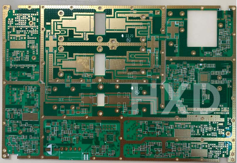
4Layer Rogers4350+FR4 with Hybrid Laminating PCB
Rogers 4350 for RF layers + FR4 for structural layers, delivering high-frequency performance with lower material cost
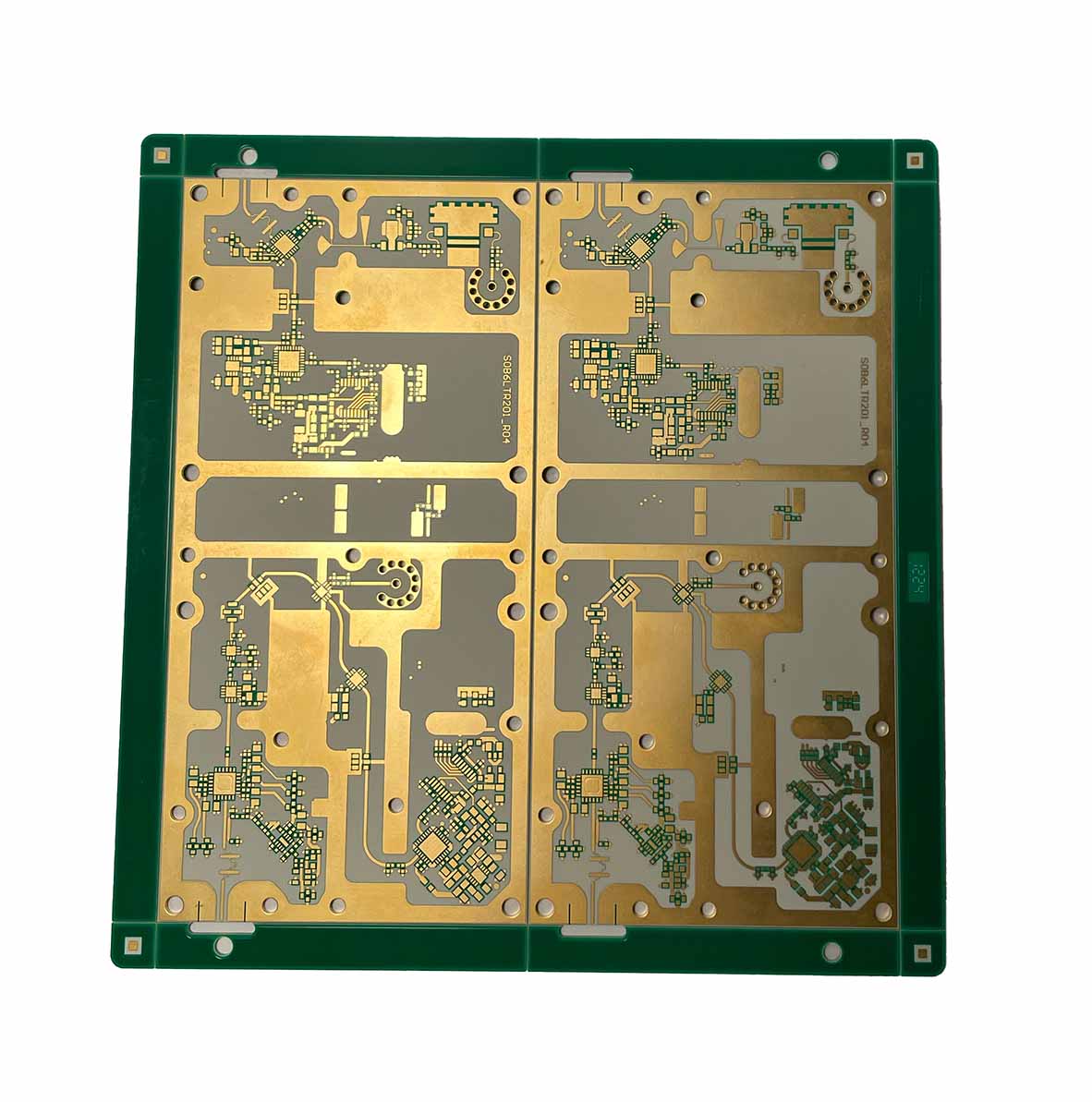
4Layer with Rogers+FR4 Hybrid Board+Copper Coin Buried
Hybrid Material: FR4 Tg170 + Rogers 4350,4-Layer Rigid Structure for Broadcasting Applications,High-Precision PCB Capability
Rogers Corporation
Rogers PCB Material Comparison
High-frequency laminate specifications — sorted by Df (@ 10GHz)
| Name | Application Areas | HDI Preferred | Dk @ 10GHz | Df @ 10GHz | Tg °C | Thermal Cond. W/m·K | Elec. Strength V/mil | Moisture Abs. % | Td °C | CTE X ppm/°C | CTE Y ppm/°C | CTE Z ppm/°C | Tensile Mod. Mpsi | Tensile Str. Kpsi | Flexural Str. Kpsi |
|---|---|---|---|---|---|---|---|---|---|---|---|---|---|---|---|
|
DiClad 880
| Very High Speed / Frequency, Very Low Loss | — | 2.17 | 0.0009 | — | 0.261 | 1300 | 0.02 | — | 25 | 34 | 252 | 0.202 | 7.5 | — |
|
RT/duroid 5880
| Very High Speed / Frequency, Very Low Loss | — | 2.2 | 0.0009 | — | 0.2 | — | 0.02 | 500 | 31 | 48 | 237 | 0.125 | — | — |
|
CLTE-XT
| Very High Speed / Frequency, Very Low Loss | — | 2.94 | 0.001 | — | 0.56 | 1000 | 0.02 | 539 | 12 | 13 | 40 | 0.26 | 3.7 | 5.8 |
|
RO3003
HDI ✓
| Very High Speed / Frequency, Very Low Loss | ✓ | 3 | 0.001 | — | 0.5 | — | 0.04 | 500 | 17 | 16 | 25 | 0.119 | — | — |
|
RT/duroid 5870
| Very High Speed / Frequency, Very Low Loss | — | 2.33 | 0.0012 | — | 0.22 | — | 0.02 | 500 | 22 | 28 | 173 | 0.185 | — | — |
|
RT/duroid 6002
| Very High Speed / Frequency, Very Low Loss, High Dk | — | 2.94 | 0.0012 | — | 0.6 | — | 0.02 | 500 | 16 | 16 | 24 | 0.12 | — | — |
|
IsoClad 917
| Normal speed, Normal Loss | — | 2.2 | 0.0013 | — | 0.263 | — | 0.04 | — | 46 | 47 | 236 | — | 3.8 | — |
|
CLTE-AT
| Very High Speed / Frequency, Very Low Loss | — | 3 | 0.0013 | — | 0.64 | 1000 | 0.03 | 529 | 8 | 8 | 20 | 0.26 | 4.4 | 7.8 |
|
RO3035
| Very High Speed / Frequency, Very Low Loss | — | 3.5 | 0.0015 | — | 0.5 | — | 0.04 | 500 | 17 | 17 | 24 | 0.145 | — | — |
|
RO3203
| Very High Speed / Frequency, Very Low Loss | — | 3.02 | 0.0016 | — | 0.48 | — | 0.1 | 500 | 13 | 13 | 58 | 0.351 | — | — |
|
TC350 Plus
| Very High Speed, Very Low Loss | — | 3.62 | 0.0017 | — | 1.24 | 650 | 0.05 | 500 | 10 | 9 | 38 | — | 6.7 | 9.4 |
|
XtremeSpeed RO1200
| Very High Speed, Very Low Loss | — | 3.05 | 0.0017 | — | 0.42 | — | 0.03 | 500 | 8 | 8 | 30 | — | — | — |
|
TMM 10
| Very High Speed / Frequency, Very Low Loss, High Dk | — | 9.2 | 0.002 | — | 0.76 | 285 | 0.09 | 425 | 21 | 21 | 20 | 1.79 | — | 13.62 |
|
TC600
| Very High Speed, Very Low Loss | — | 6.15 | 0.002 | — | 1.4 | 850 | 0.02 | 512 | 9 | 9 | 35 | — | 4.3 | 9.3 |
|
TMM 6
| Very High Speed / Frequency, Very Low Loss, High Dk | — | 6 | 0.002 | — | 0.72 | 362 | 0.06 | 425 | 18 | 18 | 26 | 1.75 | — | 15.02 |
|
TMM 3
| Very High Speed / Frequency, Very Low Loss | — | 3.27 | 0.002 | — | 0.7 | 441 | 0.06 | 425 | 15 | 15 | 23 | 1.72 | — | 16.53 |
|
AD1000
| Very High Speed / Frequency, Very Low Loss, High Dk | — | 10.2 | 0.002 | — | 0.81 | 622 | 0.03 | 500 | 8 | 10 | 20 | 0.2 | 4.3 | 7.5 |
|
TMM 4
| Very High Speed / Frequency, Very Low Loss | — | 4.5 | 0.002 | — | 0.7 | 371 | 0.07 | 425 | 16 | 16 | 21 | 1.76 | — | 15.91 |
|
TMM 10i
| Very High Speed / Frequency, Very Low Loss, High Dk | — | 9.8 | 0.002 | — | 0.76 | 267 | 0.16 | 425 | 19 | 19 | 20 | 1.8 | — | 13.62 |
|
CLTE
| Very High Speed / Frequency, Very Low Loss | — | 2.98 | 0.002 | — | 0.5 | 1100 | 0.04 | 538 | 9 | 9 | 57 | 1.05 | 10.3 | 12.6 |
|
TC350
| Very High Speed, Very Low Loss | — | 3.5 | 0.002 | — | 0.72 | 780 | 0.05 | 520 | 7 | 7 | 23 | — | 8 | 10 |
|
RO3006
| Very High Speed / Frequency, Very Low Loss, High Dk | — | 6.15 | 0.002 | — | 0.79 | — | 0.02 | 500 | 17 | 17 | 24 | 0.187 | — | — |
|
RO3010
| Very High Speed / Frequency, Very Low Loss, High Dk | — | 10.2 | 0.0022 | — | 0.95 | — | 0.05 | 500 | 13 | 11 | 16 | 0.28 | — | — |
|
RT/duroid 6010 LM
| Very High Speed / Frequency, Very Low Loss, High Dk | — | 10.2 | 0.0023 | — | 0.86 | — | 0.01 | 500 | 24 | 24 | 47 | 0.081 | — | — |
|
RT/duroid 6006
| Very High Speed / Frequency, Very Low Loss, High Dk | — | 6.15 | 0.0027 | — | 0.49 | — | 0.05 | 500 | 47 | 34 | 117 | 0.075 | — | — |
|
RO4003C
| Very High Speed / Frequency, Very Low Loss | — | 3.38 | 0.0027 | 280 | 0.71 | 780 | 0.06 | 425 | 11 | 14 | 46 | 2.821 | 14.5 | 40 |
|
RO4350B
HDI ✓
| Very High Speed / Frequency, Very Low Loss | ✓ | 3.48 | 0.0037 | 280 | 0.69 | 780 | 0.06 | 390 | 10 | 12 | 32 | 2.053 | 18.9 | 37 |
|
Magtrex 555
| Medium speed, Medium Loss | — | 6.5 | 0.01 | — | 0.47 | 131 | 0.25 | 500 | 22 | 25 | 25 | 217.7 | 1.25 | 1.54 |
|
92ML
| Medium speed, Medium Loss | — | 5.28 | 0.011 | 164 | 2.3 | 1607 | 0.12 | 404 | 18 | 18 | 27 | — | 14.1 | — |
Selection Guide
Why Choose Rogers Materials?
Rogers materials are the industry standard for high-speed, high-frequency circuits. By offering exceptional signal integrity and superior heat management, Rogers helps engineers achieve exact impedance control and long-term durability in any environment
Electrical Performance
Frequency & Signal Integrity
In 5G and millimeter-wave designs, Df is the first parameter to consider. The lower the value, the less signal loss at high frequencies.
Thermal Management
Heat & Mechanical Stability
For high-power designs, thermal conductivity should be a top priority.When evaluating thermal cycling reliability, focus on how well the Z-axis CTE matches the copper foil.
Environmental Reliability
Moisture & Harsh Environments
Manufacturability & Cost
Process & Budget Optimization
Material Guide
Common Rogers PCB Materials
A practical reference for the most widely used Rogers laminates — specs, strengths, and when to use each one.
RO4350B
DC – 40 GHzThe industry's default choice for high-frequency PCB design. Excellent balance of loss performance, processability, and cost. Compatible with standard FR4 processes and UL 94 V-0 rated — ideal for hybrid stackups.
Dk @ 10GHz
3.48 ±0.05
Df @ 10GHz
0.0037
Thermal Cond.
0.69 W/m·K
Moisture Abs.
0.06%
Best for: General high-frequency designs, 5G base station antennas, automotive communication modules, and Rogers + FR4 hybrid constructions.
RO4003C
DC – 30 GHzClosely related to RO4350B with slightly lower Df and higher Tg. No brominated flame retardants — preferred when loss performance is the top priority and flame retardancy is not required.
Dk @ 10GHz
3.55 ±0.05
Df @ 10GHz
0.0027
Thermal Cond.
0.71 W/m·K
Tg
280 °C
Best for: RF front-end modules, power amplifiers, and designs where minimum insertion loss matters more than flame-retardancy certification.
RO3003
Millimeter-WaveRogers 3003 features a ceramic-filled PTFE substrate with ultra-low Df and stable Dk, making it the preferred material for millimeter-wave (mmWave) designs.
Dk @ 10GHz
3.00 ±0.04
Df @ 10GHz
0.0010
CTE Z-axis
25 ppm/°C
Moisture Abs.
0.04%
Best for: 77GHz ADAS automotive radar front-ends, 5G millimeter-wave modules, and high-frequency applications above 30 GHz.
Not sure which material fits your design?
Share your specs — our engineers will recommend the right Rogers material for free.
FAQ
Frequently Asked Questions
Everything engineers and buyers ask us most often about Rogers PCB.