Complete Guide to High Tg PCB(2026)
What Is High Tg PCB?
A High Tg PCB is a printed circuit board made from material with a high glass transition temperature (Tg). Tg is the temperature point where the resin in the PCB changes from a hard state to a softer state.
Common Tg grades include 130°C, 150°C, 170°C, and 180°C.
A higher Tg means the PCB can handle more thermal stress during assembly and operation. It also keeps electrical performance more stable under heat. Engineers often use High Tg PCBs in industrial, automotive, and power systems to improve heat resistance and reliability.
What Problems Does High Tg PCB Solve?
Standard FR4 works well at room temperature. However, as operating temperatures rise, standard FR4 begins losing structural and electrical stability. Engineers choose High Tg PCB to prevent these failures.
Physical Damage from Heat
When a standard FR4 board operates at high temperatures, the substrate can soften and deform. This may cause layer separation. The copper inside plated through-holes can crack and break. Once this occurs, engineers cannot repair the board, and it will fail in operation.
Damage from Repeated Soldering
Lead-free soldering requires higher temperatures than older methods. Each reflow cycle puts stress on the board.
With repeated thermal cycles, heat builds over time. Standard FR4 may degrade under this stress. High Tg PCB resists this effect and maintains structural stability.
Unstable Electrical Performance
Temperature changes affect the dielectric constant (Dk) of the board material. Variations in Dk can lead to unstable impedance. In high-speed or RF designs, even small impedance changes can cause data errors.
High Tg Material Options
Parameter Explanation
| Parameter | Definition & Significance |
| Tg (Glass Transition Temperature) | Tg defines the temperature where the material starts softening. A key indicator of heat resistance. |
| Td (Thermal Decomposition Temperature) | Td is the temperature where the material begins to break down. Even if Tg is high, a low Td can cause material damage after multiple soldering cycles. |
| Z-CTE (Z-Axis Coefficient of Thermal Expansion) | Z-CTE is a key factor for via reliability. A lower CTE means less expansion in the thickness direction during heating, which helps prevent copper cracking in vias. |
| Dk (Dielectric Constant) | Dk affects signal speed. A lower Dk allows faster signal transmission. |
| Df (Dissipation Factor) | Df measures signal loss in the material. A lower Df means less energy loss and better high-frequency performance. |
Standard High Tg FR-4 usually has a Df around 0.015. If you need ultra-low loss (below 0.005), consider high-speed high Tg materials such as IT-180GN or the Megtron series.
Mainstream High Tg Materials (2026)
| Brand | Core Model | Tg | Td | Z-CTE | Dk | Df | Applications & Key Features | Official Source |
|---|---|---|---|---|---|---|---|---|
| Shengyi | S1000-2 | 170°C | 350°C | 2.6% | 4.6 | 0.015 | Widely used worldwide. Used in PC motherboards, industrial control boards, power supplies, and most general multilayer PCBs. | S1000-2 Datasheet |
| ITEQ | IT-180A | 175°C | 350°C | 2.5% | 4.4 | 0.014 | First choice for automotive and server applications. Excellent CAF resistance and thermal cycling reliability. Used in ECU, telecom base stations, and server systems. | IT-180A |
| TUC | TU-768 | 175°C | 355°C | 2.4% | 4.3 | 0.014 | Designed for HDI and high-density layouts. Excellent dimensional stability and low moisture absorption. Widely used in smartphones, tablets, and HPC boards. | TU-768 |
| Isola | 370HR | 180°C | 340°C | 2.8% | 4.17 | 0.016 | High-end material used in Europe and the US. Very stable under thermal cycling. Common in medical, aerospace, and defense-grade electronics. | 370HR |
| Nanya | NP-175 | 170°C | 345°C | 2.7% | 4.5 | 0.018 | Strong choice for mass production consumer electronics. Good cost control and stable supply. Used in LED drivers, mid-range industrial control, and consumer devices. | NP-175 Data |
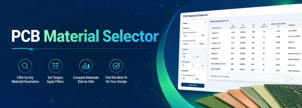
If you are comparing PCB materials, our PCB Material Selector tool can help. It lets you quickly check Tg values and material options for different uses.
8-Layer High Tg PCB Stackup Example
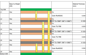
| Finished Board Thickness: | 1.65+/-10%mm |
| Layer: | 8L |
| Material: | Ro4003+Tu-768 |
| Surface Finish | ENIG |
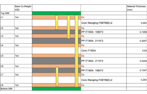
| Finished Board Thickness: | 1.8+/-10%mm |
| Layer: | 8L |
| Material: | F4BTM(E)+IT 180A |
| Surface Finish: | ENIG |
Our Recommendations
If you focus on cost control, we recommend Shengyi S1000-2. Engineers widely use this material, and suppliers maintain a stable supply. It offers strong cost performance, and most factories keep it in stock.
For harsh environments such as automotive electronics or military applications, we recommend ITEQ IT-180A or Isola 370HR. These materials offer better CAF resistance and thermal stability, making them more reliable for long-term use.
For high-layer-count PCBs (12 layers or more), we recommend materials with Z-CTE below 3.0%. This helps ensure better via reliability and long-term electrical connection stability.
As a high-tg pcb manufacturer, We offer a full range of hdi & high tg pcb solutions based on different thermal, electrical, and manufacturing requirements.
Not Sure Which High Tg Material Is Right for You?
Eco-Friendly and Special Function High Tg Materials
Environmental regulations and new technology trends are driving higher demand for two types of materials in 2026.
Halogen-Free High Tg Materials for Halogen-Free PCB Applications
- Shengyi S1170G: Tg 170°C. This material meets environmental requirements and also has a low thermal expansion coefficient.
- TUC TU-862 HF: A high-end halogen-free material. It offers both high Tg and low dielectric loss.
High-Speed High Tg Materials
- Panasonic Megtron 6 (M6): Tg above 185°C. It also provides excellent performance for high-speed signal transmission.
- TUC TU-872 SLK: Designed for low signal loss. Engineers widely use it in high-speed backplanes and switch systems.
How to Choose the Right Tg Value
Tg 150 vs. Tg 170 vs. Tg 180
Not every project needs the most expensive material. Here is a quick breakdown of where each one fits best:
| Tg Value | Category | Best Use Cases |
| Tg 150 | Mid Tg | Simple consumer electronics, toys, and basic LED lights. |
| Tg 170 | High Tg | The Industry Standard. Used for computer motherboards, industrial controllers, and telecommunications. |
| Tg 180 | Ultra High Tg | Medical equipment, aerospace technology, and heavy-duty automotive parts. |
Working Temperature: The 25°C Rule
A common mistake is picking a Tg that is exactly the same as your device’s operating temperature.
The Golden Rule: Always choose a Tg that is at least 25°C higher than the actual working temperature of the device.If your engine sensor runs at 145°C, you should use Tg 170 or higher to keep the board stable.
Leaded vs. Lead-Free Soldering
Lead-free soldering is the modern standard. It uses higher temperatures (about 217°C–260°C).
It places higher demands on PCB materials. Boards need a higher Tg (≥170°C), lower Z-CTE, and higher Td to ensure reliability.
Leaded soldering uses lower temperatures and can work with standard FR4 materials. Its reliability requirements are also lower compared to lead-free processes.
High Tg Hybrid Stackup
In actual PCB manufacturing, we often use a hybrid stackup process. Not every layer in an 8-layer or 12-layer board requires expensive High Tg material. Instead, we use a mixed material structure to balance performance and cost.
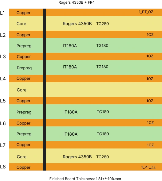
High Tg Material in Critical Layers
- Outer Layers: These layers face high heat during reflow soldering and assembly.
- Critical Signal Layers: Used for high-speed signals. They keep the Dk stable during temperature changes.
Standard FR-4 in Other Layers
Standard FR-4 is usually used in non-critical areas or filler layers:
- Inner Cores: These layers are not directly exposed to surface heat stress.
- Structural Support Layers: They provide mechanical strength and board thickness.
- Cost Optimization Layers: They help reduce the overall material cost.
Conclusion
High Tg PCB materials help improve heat resistance, and electrical stability in demanding environments. The right choice depends on your application, not just the Tg value. For most projects, balancing cost, performance, and manufacturing needs is the best approach. By understanding Tg, Z-CTE, and loss factors, you can choose the right material and improve long-term product reliability.
FAQ