
PCB Certifications






| Product | 6 Layer 1.6 mm 35 µm ENIG |
| Stackup | open |
| Surface finish | ENIG |
| Base material | FR4 TG 150°C |
| PCB Thickness | 1.6mm (63 mil) |
| Copper thickness | 35µm on all Layers |
Standard 6-Layer PCB Options
A 6-layer PCB is a multilayer board with four signal layers and two internal planes, usually ground and power.
It provides better EMI shielding than a 4-layer PCB. At the same time, it avoids the higher cost of 8-layer or more complex designs.
The table on the left shows a standard 6-layer options for fast production. If you require a specific material or a custom stackup, please use our PCB material selector and PCB stackup design tool , then contact us for a quote.
Real-World References
6-Layer PCB Stackup Examples
Real stackup configurations from HXDcircuit production orders — use these as a reference when specifying your 6-layer PCB material and surface finish.
6-Layer PCB Stackup Example 1
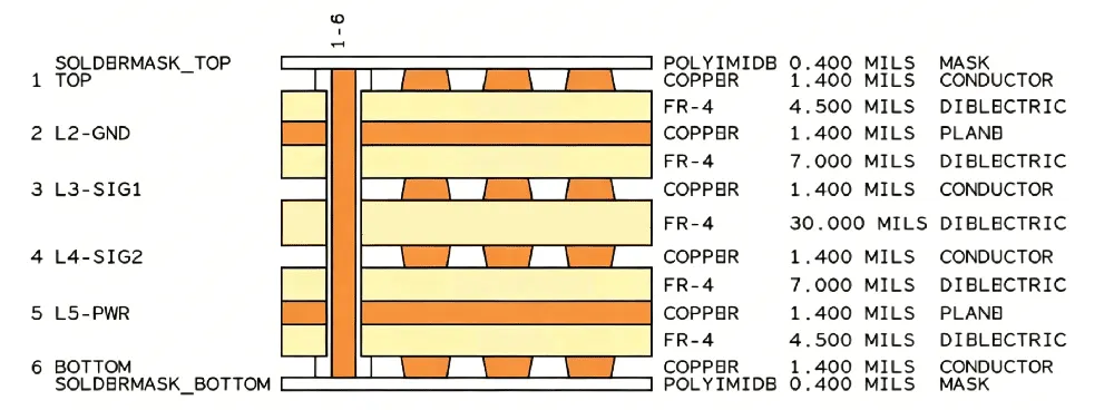
| Finished Board Thickness: | 1.6+/-2%mm |
| Min. Line Width / Spacing | 6/6 mil |
| Material: | FR4 Tg135 |
| Surface Finish: | Immersion Gold |
| Certification | IPC-6012E Class II |
| No | Imp Type | Ctrl | Up Ref | Dn Ref | Trace W | Trace S | IMP_Req |
|---|---|---|---|---|---|---|---|
| 1 | Single-ended | L1 | L2 | 7 | 50 | ||
| 2 | Differential | ||||||
| 3 | Single-ended | L3 | L2 | L4 | 8 | 50 | |
| 4 | Differential | ||||||
| 5 | Single-ended | L4 | L3 | L5 | 8 | 50 | |
| 6 | Differential | ||||||
| 7 | Single-ended | L6 | L5 | 7 | 50 | ||
| 8 | Differential |
This is the most common 6-layer PCB stackup: Signal-GND-Sig-Sig-PWR-Signal. It uses ground and power planes to improve signal integrity. Inner layer routing reduces crosstalk, and the layer structure helps lower EMI. This design balances cost and high-speed performance. Click to view product images.
6-Layer PCB Stackup Example 2
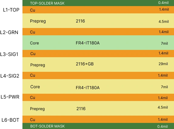
| Finished Board Thickness: | 1.6+/-10%mm |
| Min. Line Width / Spacing | 5/5 mil |
| Material: | FR4 TG170 |
| Surface Finish: | Immersion Gold |
| Certification | IPC-6012E Class II |
| No | Imp Type | Ctrl | Up Ref | Dn Ref | Trace W | Trace S | IMP_Req |
|---|---|---|---|---|---|---|---|
| 1 | Single-ended | L1 | L2 | 7 | 50 | ||
| 2 | Differential | L1 | L2 | 5.5 | 9.5 | 100 | |
| 3 | Single-ended | L3 | L2 | L5 | 8 | 50 | |
| 4 | Differential | L3 | L2 | L5 | 5.5 | 9.5 | 100 |
| 5 | Single-ended | L4 | L2 | L5 | 8 | 50 | |
| 6 | Differential | L4 | L2 | L5 | 5.5 | 9.5 | |
| 7 | Single-ended | L6 | L5 | 7 | 50 | ||
| 8 | Differential | L6 | L5 | 5.5 | 9.5 | 100 |
This stackup features a symmetrical structure and high-Tg material (IT-180A) for better thermal stability. The thicker core layer improves insulation and reduces layer coupling. HXD designed this industrial-grade PCB specifically for American customers. It’s a great choice for industrial PCBs, especially in power systems and control equipment. View Product Imgaes
6-Layer PCB Stackup Example 3
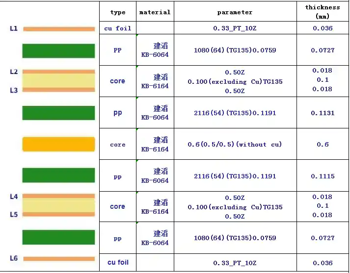
| Finished Board Thickness: | 1.41+/-10%mm |
| Min. Line Width / Spacing | 5/5 mil |
| Material: | FR4 TG135 |
| Surface Finish: | Immersion Gold |
| Certification | IPC-6012E Class II |
| No. | type | control layer | ref layer | orig width (Mil) | orig space (Mil) | adjusted width (Mil) | adjusted space (Mil) | required impedance value (OHM) | actual impedance value (OHM) |
|---|---|---|---|---|---|---|---|---|---|
| 1 | single-ended | L3 | L2/L5 | 4.764 | 4.764 | 50 | 50.99±5 | ||
| 2 | single-ended | L4 | L2/L5 | 4.764 | 4.764 | 50 | 50.99±5 | ||
| 3 | differential | L3 | L2/L4 | 4.13 | 5 | 3.4 | 5.73 | 100 | 99.22±10 |
| 4 | single-ended | L1 | L2 | 4.764 | 4.3 | 50 | 49.84±5 | ||
| 5 | single-ended | L6 | L5 | 4.764 | 4.3 | 50 | 49.84±5 | ||
| 6 | differential | L1 | L2 | 4.748 | 5 | 3.4 | 6.348 | 100 | 99.84±10 |
This 6-layer PCB stackup uses a symmetrical design with KB-6164/KB-6064 (TG135) material from Kingboard. It offers good thermal stability, and cost-effective performance for industrial applications. View Product Images
HXD has over 20 years of PCB manufacturing experience. We have delivered solutions for many industries, including industrial control, automotive electronics, and consumer electronics. In addition to the rigid PCB stackups above, we also offer 6-layer rigid-flex PCB stackups.
Technical Specs
6-Layer PCB Manufacturing Capabilities
HXD provides 6-layer PCB manufacturing with stackup design, material options, copper thickness, and precision production for various applications.
| Items | Standard PCB | Advanced PCB |
|---|---|---|
| Finished Board Thickness | 16~128 mil (0.4mm – 3.2mm) | / |
| Max. Panel Size | 24 × 28.5″ (622mm × 723mm) | 24 × 40″ (622mm × 1000mm) |
| Laminate Materials | FR-4, CEM-3, Mid Tg, High Tg, High CTI, Halogen Free | / |
| Finished Board Thickness Tolerance | < 1.0mm ±0.10mm (±4mil) 1.0~1.6mm ±0.15mm (±6mil) |
< 1.0mm ±0.075mm (±3mil) 1.0~1.6mm ±0.10mm (±4mil) |
| Min. Inner Thin Core Thickness | 3mil (0.075mm) | / |
| Min. Inner Line Width / Spacing | 2.5 / 3.5 mil (0.0635 / 0.089mm) | 2.5 / 2.5 mil (0.0635mm) |
| Min. Outer Line Width / Spacing | 3.5 / 3.5 mil (0.089 / 0.089mm) | 3.0 / 3.0 mil (0.075 / 0.075mm) |
| Copper Foil Thickness | 12μm, 18μm, 35μm, 70μm, 105μm, 140μm (1/3oz – 4oz) | / |
| Min. Finished Hole Size | 0.2mm | 0.15mm |
| Min. Drilling Bit Size | 0.2mm | / |
| Max. Drilling Bit Size | 6.5mm | / |
| PTH Hole Copper Thickness | 20–30μm | 10–15μm |
| Max. Aspect Ratio | ≤ 10:1 | 12:1 |
| Min. Solder Mask Opening | 0.05mm (2mil) | 0.02mm (0.8mil) |
| Surface Finish | OSP, Peelable Solder Mask, Carbon Ink, HASL (lead free), ENIG, I-Ag, I-Tin | OSP, Peelable Solder Mask, Carbon Ink, HASL (lead free), ENIG, I-Ag, I-Tin |
| E-Test Voltage | 250 ± 5V | / |
| Max. E/T Insulation Resistance | 100 MΩ | / |
In addition to 6-layer PCBs, we produce 8-layer PCB, 10-layer PCB, and 12-layer PCB boards.These are ideal for complex and high-performance applications.
Ready to Build your 6-Layer PCB?
No MOQ — upload your Gerber files and receive a quote in minutes. Prototype quantities ship in 24 hours. ISO 9001 certified factory, global shipping available.
Key Benefits of 6-Layer PCB
6-layer PCBs improve electrical performance and routing flexibility while keeping production practical and cost-efficient.
Better signal integrity
Dedicated ground and power planes reduce noise and signal loss. This helps maintain clean and stable signal transmission.
Improved EMI control
More layers allow better shielding between signals. This reduces electromagnetic interference in high-speed designs.
Higher routing density
Extra layers provide more space for complex routing. Engineers can design tighter layouts without signal conflicts.
Stable power distribution
Internal power planes deliver consistent voltage across the board. This improves performance and system reliability.
Better thermal performance
HXD also offers rigid-flex PCB stackups—click here to learn more.
More copper layers help spread heat efficiently. This supports stable operation in high-power applications.
Our Facility
Advanced Equipment for 6-Layer PCB Manufacturing
HXD has more than 15 years of experience in multilayer PCB production. We keep investing in the latest manufacturing and inspection machines. We keep our equipment in great shape, including laser direct imaging and high-precision lamination presses. This ensures your boards are perfect every time.
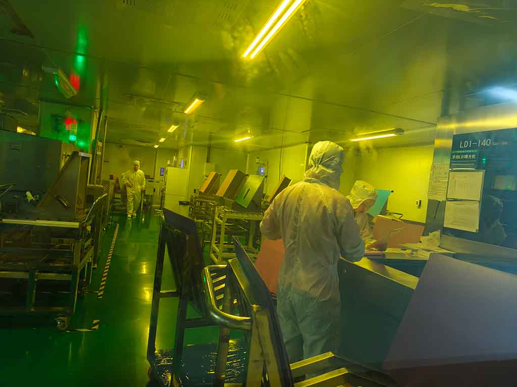
LDI Exposure
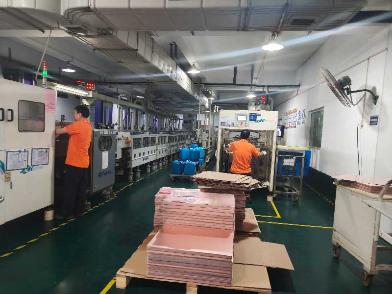
Etching
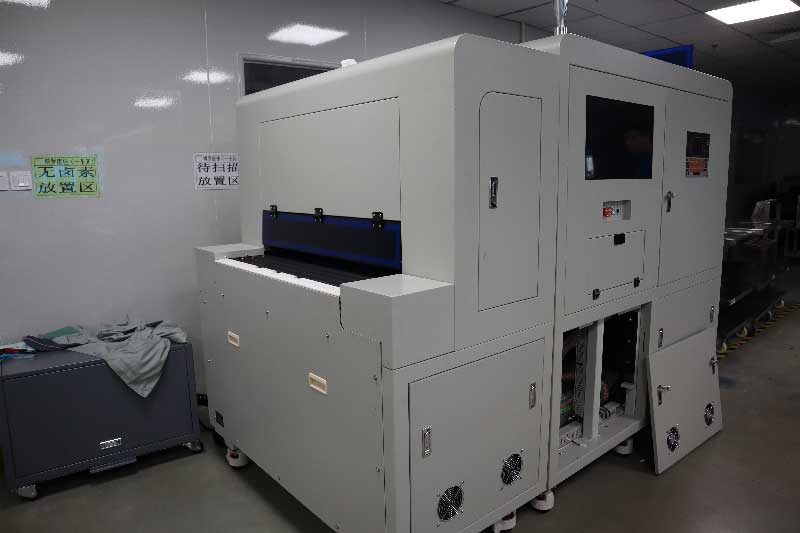
Inner AOI
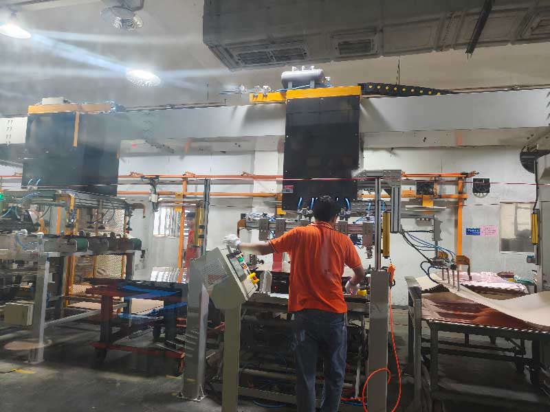
Innerlayer Laminating
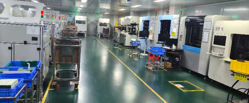
E-test
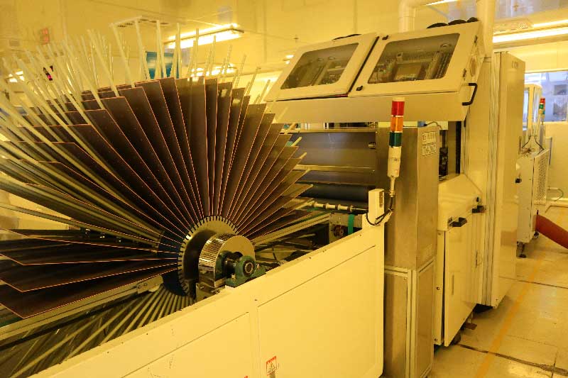
Automatic Dry Film Laminator
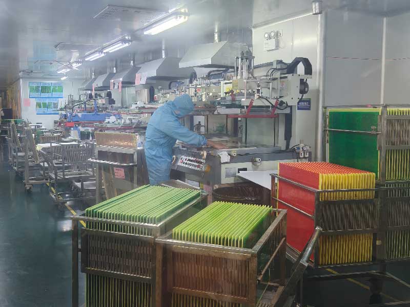
Semi Auto Legend Printing
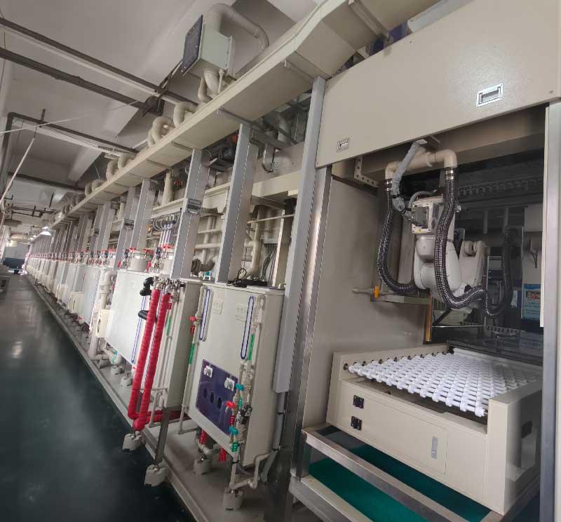
VCP Plating
Applications of 6-Layer PCB

Industrial control
Engineers use these 6-layer PCBs in PLC systems and motor controllers. They include dedicated ground planes to reduce noise and improve stability. This helps the systems run accurately in strong electromagnetic environments, such as modern smart factories.
Communication equipment
Support 10GbE switches and high-speed routers with optimized impedance control. Our 6-layer stackups minimize crosstalk and signal loss, making them ideal for high-bandwidth telecommunications infrastructure.

Automotive electronics
In automotive applications, reliability is essential. 6-layer PCBs help reduce noise, manage heat, and improve system stability under vibration.

Medical devices
Our 6-layer PCBs are used in MRI and CT scanner interfaces. We often use Isola or Taconic materials to ensure strong signal integrity. This supports high-resolution medical imaging and accurate patient monitoring.
FAQ