HXDcircuit

PTFE PCB Manufacturing

We manufacture PTFE PCBs using Rogers RO4003C, RO4350B, RT/duroid 5880, and more. Built for high-frequency, low-loss RF and microwave applications.

What Is PTFE PCB

PTFE (Polytetrafluoroethylene) is a material used as a dielectric substrate in high-frequency printed circuit boards. In PCB manufacturing, the “Teflon” brand is very well known. Because of this, PTFE PCBs are often simply called “Teflon PCBs” when people talk about high-frequency PCB materials.

PTFE has an extremely low dielectric constant (Dk) and a near-zero loss tangent (Df). These properties make it ideal for RF and microwave circuit design.

FR4 is suitable for most digital circuits.  But when the frequency goes above 1GHz, FR4 begins showing signal loss and thermal stability problems. The dielectric constant also becomes less stable, which affects circuit performance.

PTFE offers more stable electrical performance at high frequencies. Its Dk stays stable over a wide frequency range. Its Df stays extremely low, even at millimeter-wave frequencies.

In applications such as 5G communication, radar systems, and satellite navigation, engineers often use PTFE materials to meet strict electrical performance requirements.

Technical Specs

PTFE PCB Specifications

At HXD, we use several types of PTFE materials, including Rogers RO3003, RO3035, RO3006, and RT6010.2LM. Below are their key parameters:

Name Dk
@ 10GHz
Df
@ 10GHz
Tg
°C
Thermal Cond.
W/m·K
Elec. Strength
V/mil
Moisture Abs.
%
Td
°C
CTE X
ppm/°C
CTE Y
ppm/°C
CTE Z
ppm/°C
Tensile Mod.
Mpsi
Tensile Str.
Kpsi
Flexural Str.
Kpsi
RT/duroid 5880
2.2 0.0009 0.2 0.02 500 31 48 237 0.125
RO3003
3 0.001 0.5 0.04 500 17 16 25 0.119
RT/duroid 5870
2.33 0.0012 0.22 0.02 500 22 28 173 0.185
RT/duroid 6002
2.94 0.0012 0.6 0.02 500 16 16 24 0.12
RO3035
3.5 0.0015 0.5 0.04 500 17 17 24 0.145
RO3203
3.02 0.0016 0.48 0.1 500 13 13 58 0.351
AD1000
10.2 0.002 0.81 622 0.03 500 8 10 20 0.2 4.3 7.5
RO3006
6.15 0.002 0.79 0.02 500 17 17 24 0.187
RO3010
10.2 0.0022 0.95 0.05 500 13 11 16 0.28
RT/duroid 6010 LM
10.2 0.0023 0.86 0.01 500 24 24 47 0.081
RT/duroid 6006
6.15 0.0027 0.49 0.05 500 47 34 117 0.075
RO4350B
3.48 0.0037 280 0.69 780 0.06 390 10 12 32 2.053 18.9 37

In PCB manufacturing, pure PTFE is rarely used by itself because it has low mechanical strength and is hard to process. Manufacturers usually add reinforcing materials, such as glass fiber, or ceramic fillers to improve its performance.

We also use the F4B series from Wangling, China. This series offers high performance at a lower cost. Below are the key parameters of the F4B materials:

Name Dk(εr)@10G Df(tgδ)@10G TcDk ppm/ºC CTE Z ppm/ºC Material Features
Typical Value
F4BTM298 2.98±0.06 0.0018 -78 78 Glass Fiber Fabric with ED Copper Foil

DK2.98~3.5,DF0.0018~0.0025

F4BTME with RTF copper foil offers excellent PIM performance.

Available in many thickness options.

Available in different sizes to help save cost.

F4BTM300 3.00±0.06 0.0018 -75 72
F4BTM320 3.20±0.06 0.0020 -75 58
F4BTM350 3.50±0.07 0.0025 -60 51
F4BTME298 2.98±0.06 0.0018 -78 78
F4BTME300 3.00±0.06 0.0018 -75 72
F4BTME320 3.20±0.06 0.0020 -75 58
F4BTME350 3.50±0.07 0.0025 -60 51
Get a Quote

Ready to Start Your PTFE PCB Project?

Upload your Gerber files or share your design requirements. Our engineering team will review your specs and get back to you within 24 hours with a detailed quote.

Quote within 2 hours DFM review included IPC-A-600 certified

Key Advantages of PTFE PCB

Low DF

PTFE substrates have a near-zero loss tangent(0.0005~0.002).

Signal transmission loss is more than 80% lower than FR4, making it suitable for millimeter-wave bands such as 5G 28/39 GHz.

Stable DK

PTFE has a highly symmetrical molecular structure and extremely low polarity.

In the 1–100 GHz high-frequency range, the dielectric constant (Dk) varies by less than ±0.02. This keeps the signal phase stable during transmission.

Environmental stability

Temperature range (-200°C to +260°C): Dk and Df stay stable even at high temperatures. This makes PTFE suitable for harsh environments such as aerospace and automotive radar systems.

Moisture resistance
: Water absorption is less than 0.01%, which helps prevent signal distortion caused by changes in humidity.

Suitable for millimeter-wave frequencies

PTFE laminates support signal integrity at frequencies from 1GHz up to 77GHz and beyond.

They are the standard choice for automotive radar, 5G mmWave, and satellite communication hardware.

PTFE PCB Manufacturing Challenges

We also use the F4B series from Wangling, China. This series offers high performance at a lower cost. Below are the key parameters of the F4B materials:PTFE PCBs offer excellent electrical performance. However, their material properties create major challenges in manufacturing. These properties include softness, a non-stick surface, and a high thermal expansion coefficient.

storage

Handling & Storage

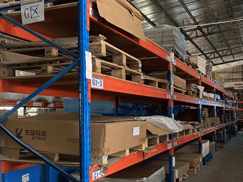
PTFE substrates are relatively soft and can be easily scratched or dented during handling. Place soft protective material between boards during transport.

Operators should wear lint-free gloves to avoid surface dirt. Store the material in a cool, dry, and dark environment, and use it within 40 days when possible.
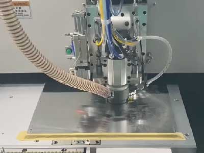
pcb-drilling

Drilling

PTFE has some flexibility, which can cause burrs or hole deformation during drilling.

Use a high-speed spindle (180,000–250,000 RPM) with a low feed rate. Use phenolic or aluminum backing plates to improve drilling stability.

For micro-vias, CO₂ laser drilling provides higher accuracy.
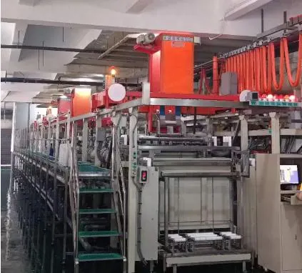
Surface Preparation

Surface Preparation

Before hole plating, factories usually perform surface activation first.

Plasma treatment or sodium naphthalene treatment can effectively improve hole wall bonding.

Since the activated surface is time-sensitive, the following copper plating process must be completed within 4 hours.

PTH Plated Through-Hole-Production Line

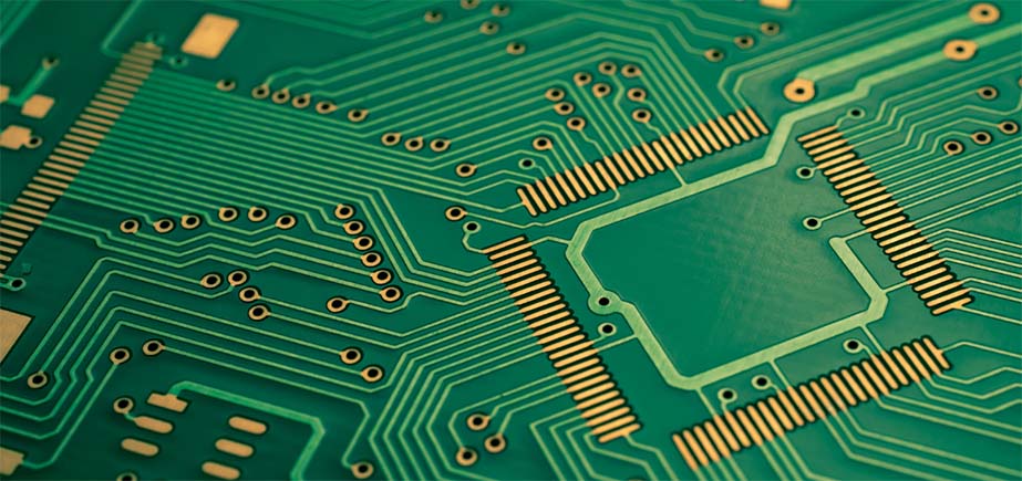
PTH & Copper Plating

PTFE has a relatively high Z-axis thermal expansion coefficient.

At high temperatures, this creates stress on hole walls. To ensure reliability, the plated copper must have high tensile strength.

This helps reduce the risk of barrel cracking and pad lifting, and improves overall structural stability.

Advanced Equipment for PCB Manufacturing

HXD has more than 15 years of experience in multilayer PCB production. We keep investing in the latest manufacturing and inspection machines. We keep our equipment in great shape, including laser direct imaging and high-precision lamination presses. This ensures your boards are perfect every time.

X-ray Target Drilling

X-ray Target Drilling

PTH Plated Through-Hole-Production Line

PTH Plated Through-Hole-Production LineEtching

pcb-Inner-AOI

Inner AOI

OPE Punching Production Line

OPE Punching Production Line

PCB Chemical Pre-treatment Line

PCB Chemical Pre-treatment Line

Automatic-Dry-Film-Laminator

Automatic Dry Film Laminator

Semi-Auto-Legend-Printing

Semi Auto Legend Printing

VCP-Plating

VCP Plating

15+
Years Manufacturing Experience
50+
Advanced Production Machines
3,000㎡
Clean-Room Production Area
ISO
9001 · UL · IPC Certified

About PTFE PCBs

Why are PTFE PCBs more expensive than standard PCBs?
PTFE PCBs cost more because the materials are expensive. Brands like Rogers and Taconic have higher prices than FR4. The process is also more complex. PTFE needs high-temperature lamination, laser drilling, and special surface treatment. The production time is longer as well.
Can PTFE and FR4 be used in the same PCB?
Yes, you can use both in one board. This is called a hybrid stackup. Engineers use PTFE in key signal layers. They use FR4 in power or control layers. This helps balance performance and cost.
What surface finishes work with PTFE PCBs?
ENIG is the most common surface finish for PTFE PCBs. It gives a flat surface and good soldering performance. It also has a long shelf life. Immersion Silver is another option. It helps reduce signal loss. Many engineers use it for high-frequency designs. HASL is not recommended. Its uneven surface can affect impedance at high frequencies.
Can PTFE PCBs be used in multilayer designs?
Yes, PTFE PCBs can be used in multilayer designs. Most boards have 2 to 20 layers. Engineers use them in antenna systems, radar modules, and microwave devices. These boards need special low-loss prepreg. This helps keep good electrical performance between layers.
How is impedance controlled in PTFE PCBs?
Impedance control in PTFE PCBs is similar to FR4. Trace width, dielectric thickness, and copper weight all affect impedance. PTFE has more stable Dk values. This makes impedance easier to control. Most manufacturers can keep tolerance within ±5%. Some can reach ±3% for critical designs.
What certifications should a PTFE PCB manufacturer have?
Choose manufacturers with ISO 9001 certification. This shows good quality control. UL certification is also important for safety and materials. For aerospace and defense, AS9100 is a good sign. It shows strong process control. IPC-A-600 and IPC-6012 are also useful standards for PCB quality.
REQUEST A QUOTE

Supported file formats: PDF, DOC, DOCX, TXT, JPG, PNG (Max 2MB)