PCB Material Properties Guide for Selection
Introduction
For engineers, PCB material selection starts with understanding the key material properties of each laminate. These properties affect signal speed, impedance control, heat resistance, mechanical strength, and long-term performance.
This guide explains the main properties used in PCB material selection. It covers material type, chemical properties, IPC and slash number, electrical properties, and thermal properties.By understanding these values, engineers can compare materials more clearly and choose a better option for each PCB application.
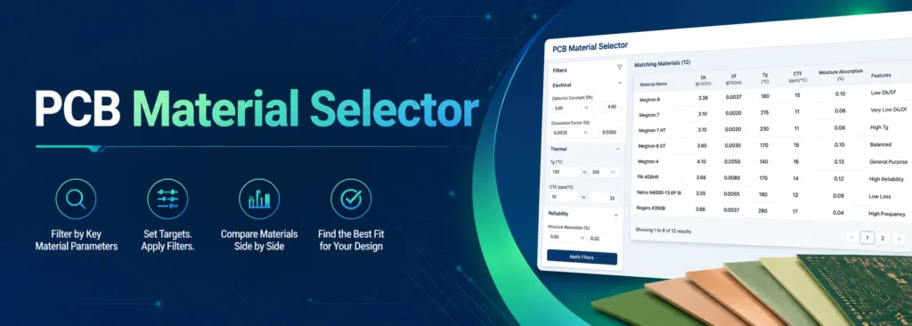
Already know the basics? Use the PCB Material Selector to find materials that match your needs.
Material Type
Material type defines the basic physical form of the PCB material. The main types include rigid PCB material, and flex PCB material.
Rigid PCBs commonly use FR-4 materials because they offer a good balance of cost, strength, and manufacturability. FR-4 is made from epoxy resin and woven glass fiber, making it suitable for most standard double-sided, and multilayer PCBs.
Flex PCB uses polyimide-based materials that can bend and fold. A circuit is useful when it must fit in a tight space or move during use. Examples include endoscopes, wearable devices, and cable-replacement connections. Unlike rigid PCB, flex PCB uses different base materials, coverlay, and copper types.
The same material name does not always mean the same construction.
For example, FR-4 behaves differently in a rigid PCB than in a flex PCB. The resin system, glass weave, copper type, and coverlay may all change. This is why material type should be the first choice in PCB material selection.
Chemical Properties
Chemical properties show how a PCB material reacts to moisture, heat, voltage, and the working environment. These properties are important for long-term reliability.
Two chemical-related factors are especially useful during PCB material selection: Moisture Absorption and CAF Resistant.
Moisture Absorption
Moisture Absorption means how much water a PCB material can absorb under controlled test conditions. A lower value is usually better. When a PCB material absorbs too much moisture, it may affect insulation, and soldering reliability. Moisture can also increase the risk of defects during assembly, especially when the board goes through high-temperature soldering.
Most PCB materials have low moisture absorption values, but small differences still matter in demanding applications. For medical devices, automotive electronics, telecom equipment, and industrial control boards, materials with lower moisture absorption are often a safer choice.
CAF Resistant
CAF Resistant means the material has better resistance to conductive anodic filament growth. CAF is a failure mode caused by electrochemical migration inside the PCB material. It can happen under voltage, humidity, and long-term electrical stress.
If CAF forms inside the laminate, it may cause leakage current, insulation failure, or short circuits.
IPC and Slash Number
IPC standards help engineers, and PCB manufacturers describe material requirements in a clear way. IPC-4101 is a common standard for base materials used in rigid and multilayer PCBs.
A slash number is the material category under that IPC standard. For example, IPC-4101/126 means tells the manufacturer what type of material performance they need.
This is more accurate than writing only “FR-4” in a drawing or purchase document. FR-4 is a broad material family. IPC slash numbers make the requirement more specific.
Here is a simple reference:
| Slash Number | ANSI Type | Tg | Typical Use |
| /99, /124 | FR-4 | >150°C | Standard multilayer PCBs with good availability |
| /126, /129 | FR-4 | >170°C | Thicker boards and multiple reflow cycles |
| /125, /128 | HF-FR4 | >150°C | Halogen-free requirements |
| /130, /131 | HF-FR4 | >170°C | Halogen-free and high-Tg needs |
IPC slash numbers are useful, but they should not be the only selection rule. Different brands under the same slash number may still have different Dk, Df, CTE, moisture absorption, and process behavior. You can search by IPC slash number directly in the PCB Material Selector.
Electrical Properties
Electrical properties show how a PCB material affects signal transmission and insulation. These values are critical for high-speed PCB, and controlled impedance designs.
Dk
Dk(Dielectric Constant) affects signal speed and impedance calculation. It shows how much a PCB material slows down an electrical signal compared with free space.
A lower Dk usually allows faster signal propagation. A stable Dk helps designers control impedance more accurately across frequency. Most PCB materials have Dk values in a general range.
Standard FR-4 often has a Dk around 4.0 to 4.5 at low frequency. But Dk can change as frequency rises.
Df
Df (Dissipation Factor / Loss Tangent) — Df shows how much signal energy is lost in the dielectric material. A higher Df means more signal energy turns into heat as the signal travels through the PCB.
At low frequencies, this loss may be small. At higher frequencies, especially around 10 GHz and above, Df becomes much more important. High dielectric loss can reduce signal quality and make high-speed designs harder to pass.
Typical Df ranges by material category:
- Standard FR-4: about 0.020–0.025 at 10 GHz
- Low-loss FR-4 alternatives: about 0.006–0.010 at 10 GHz
- RF / microwave laminates: about 0.001–0.004 at 10 GHz
Both Dk and Df can change as frequency increases. This is why you should not rely only on the 1 MHz value in a datasheet.
For high-speed and microwave PCB designs, check Dk and Df values measured near your operating frequency.
Dielectric Electrical Strength
Dielectric Electrical Strength shows how much voltage a PCB material can withstand before electrical breakdown occurs. It measures the insulation strength of the dielectric material, usually in V/mil. A higher value means the material can handle stronger electric fields without losing insulation performance.
For example, Rogers RO4350B has a dielectric electrical strength of 780 V/mil. FR408HR, an FR-4 laminate, has a dielectric electrical strength of 1740V/mil.
Most IPC-certified PCB materials have a dielectric electrical strength of at least 750 V/mil.
When designing power electronics, industrial control boards, or automotive PCBs, Dielectric Electrical Strength is an important factor. It helps confirm safe electrical isolation.
Thermal Properties
Thermal properties show how a PCB material behaves under heat. These values affect assembly, long-term reliability, and plated through-hole reliability.
Tg
Tg (Glass Transition Temperature) is the temperature range where a material changes from hard and glassy to softer. When the material cools below Tg, its properties can return to normal. Standard FR-4 may use lower Tg values, while high-Tg FR-4 is better for higher heat stress.
Td
Td (Decomposition temperature) is the temperature where the material starts chemically breaking down and losing mass. The PDF notes that changes after Td are not reversible, so Td must be well above the assembly temperature range.
CTE
CTE(Coefficient of Thermal Expansion) shows how much the material expands when heated. Z-axis CTE is especially important because the laminate expands more in the thickness direction than copper. This can place stress on plated through-holes and vias.
X and Y-axis CTE are usually lower because woven glass limits expansion. Z-axis expansion should stay as low as possible.
Thermal conductivity
Thermal conductivity also matters. It shows how well heat moves through a material. Most PCB dielectric materials have much lower thermal conductivity than copper. For high-power, LED, and heat-sensitive products, designers should check thermal conductivity early.
Mechanical Properties
Mechanical properties show how well a PCB material can handle force, bending, and physical stress. These values matter more when the PCB is in a high-stress environment, like automotive electronics or industrial equipment.
Tensile Modulus
Tensile modulus is also called Young’s modulus. It shows how much a material resists stretching under force. A higher value means the material is harder to deform. This parameter helps engineers understand how the material may behave under mechanical load.
Tensile Strength
Tensile strength shows the maximum pulling stress a material can take before it breaks. This is useful when the PCB may face stretching, vibration, or mechanical force during assembly or use.
Flexural Strength
Flexural strength is also called bend strength. It shows how much bending stress a material can handle before it cracks or breaks. This value is important for boards that may bend during handling, assembly, or operation.
For most standard rigid PCBs, mechanical properties are not the first selection factor. But for flex PCBs, rigid-flex PCBs, wearable electronics, and other high-reliability products, review these values carefully.
How to Choose the Right PCB Material
High-Frequency and RF Applications
For high-frequency PCB, 5G devices, and microwave circuits, signal loss is usually the first concern. Focus on low Df, stable Dk, and suitable copper foil. A material with low Df can reduce dielectric loss, while stable Dk can support better impedance control.
Low-loss materials, Rogers materials, PTFE laminates, and other RF-grade materials may work better for these designs.
High-Reliability Multilayer Boards
For servers, industrial control boards, automotive electronics, and thick multilayer PCBs, thermal reliability becomes more important. These designs may go through more heat cycles during assembly and operation.
Key values include Tg, Td, T288, and Z-axis CTE. A high Tg material can handle more heat stress.
A higher Td gives more safety margin before material breakdown. A lower Z-axis CTE can reduce stress on plated holes.
If the board is thick or must pass multiple reflow cycles, you should consider higher-grade FR-4 materials such as IPC-4101/126.
Conclusion
Many people may only choose material names they already know, and miss better options for their projects.
The parameters covered in this guide are the same filters used in the Material Selector Tool. You can set your target values, apply the filters, and compare the materials that meet your requirements.
Start selecting your PCB material?
FAQ
Frequently Asked Questions
What is T288 and why does it matter for PCB manufacturing?
How does CTE affect PCB via reliability?
What is the difference between halogen-free FR-4 and standard FR-4?
How do I choose between IPC-4101/126 and /129?
IPC-4101/129 materials come from fewer sources and typically carry longer lead times. Unless a specific /129 material has a performance advantage relevant to your design, /126 is the more predictable choice for production.