Rogers RO4350B PCB: Datasheet, Stackup, and Material Selection
Think Deeper with AI:
Introduction
Rogers 4350B is one of the most common high-frequency PCB materials used in RF and microwave designs. Engineers often choose it when FR4 loss becomes too high, but full PTFE material feels too costly or hard to build.
This guide explains RO4350B in practical terms. It covers material properties, stackup choices, rogers 4350 dielectric constant, fabrication points. It also compares rogers 4350B vs fr4, and RO4003C.
What Is RO4350B Material?
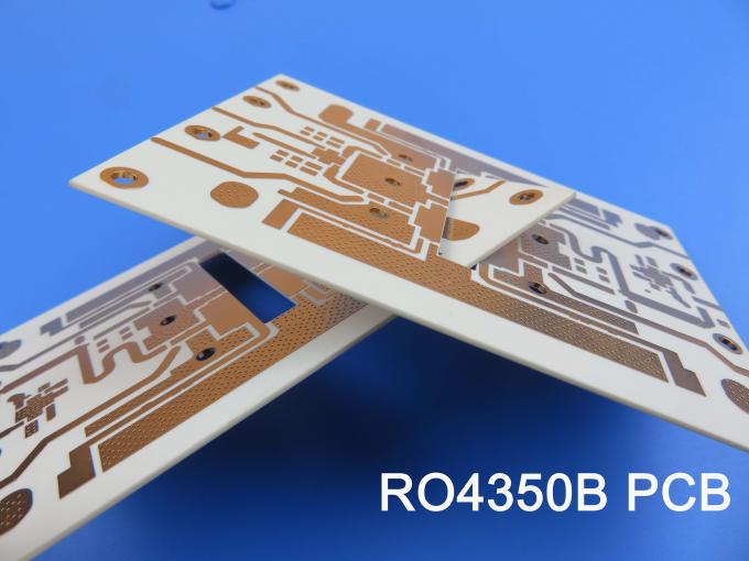
RO4350B is a hydrocarbon ceramic-filled laminate from Rogers Corporation. It belongs to the RO4000 series of high-frequency circuit materials.
RO4350B works with standard FR4 manufacturing steps. You don’t need special drilling or plating processes like you do with PTFE materials.
The main value of RO4350B is balance. It offers lower loss than normal FR4 and better process control than many PTFE laminates. It also supports mixed stackups with FR4 when the design allows it.
RO4350B is a practical choice for hybrid PCB designs. Designers can place RF layers on RO4350B and keep digital or power layers on FR4. This structure can reduce cost without losing RF performance in critical areas.
Rogers 4350B datasheet
Before you start a design, open the Rogers 4350B datasheet. Check these four values: dielectric constant, dissipation factor, thermal conductivity, and Z-axis CTE.
These values drive almost every decision in your stackup.
| Category | Parameter | Value |
|---|---|---|
| Electrical Properties | Dielectric Constant (εr) | 3.48 |
| Dielectric Tolerance | ±0.05 | |
| Dk Tolerance | ±0.002 (up to 10 GHz) | |
| Loss Tangent | 0.0037 | |
| Dissipation Factor | 0.0019 (10 GHz) | |
| Breakdown Voltage | 1.5 kV/mil | |
| Surface Resistivity | 1.5 × 10¹³ Ω | |
| Volume Resistivity | 1 × 10¹⁵ Ω·cm | |
| Thermal Properties | Z-Axis CTE | 41 ppm/°C |
| XY CTE | 17 ppm/°C | |
| Tg | 280°C | |
| Td | 340°C | |
| Thermal Conductivity | 0.69 W/m·K | |
| Lead-Free Process | 260°C Max | |
| Mechanical Properties | Moisture Absorption | <0.2% |
| Copper Peel Strength | 1.3 lb/in |
Types of RO4350B PCB
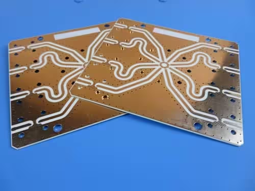
A full RO4350B stackup uses RO4350B on every dielectric layer. This structure provides the best RF performance, but it also has the highest material cost. It is usually used when most of the board carries high-frequency signals, such as antenna arrays or RF front-end modules.
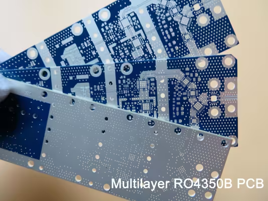
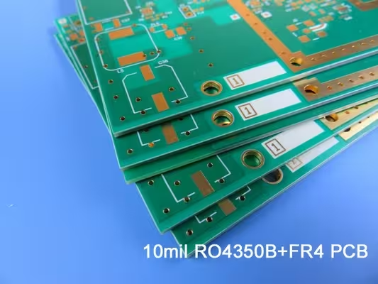
A hybrid stackup combines RO4350B with FR4. The RF layers use RO4350B, while digital, control, or power layers use FR4. This approach reduces cost while keeping low-loss material only where it is needed. Many 5G, radar, and communication boards use this structure.
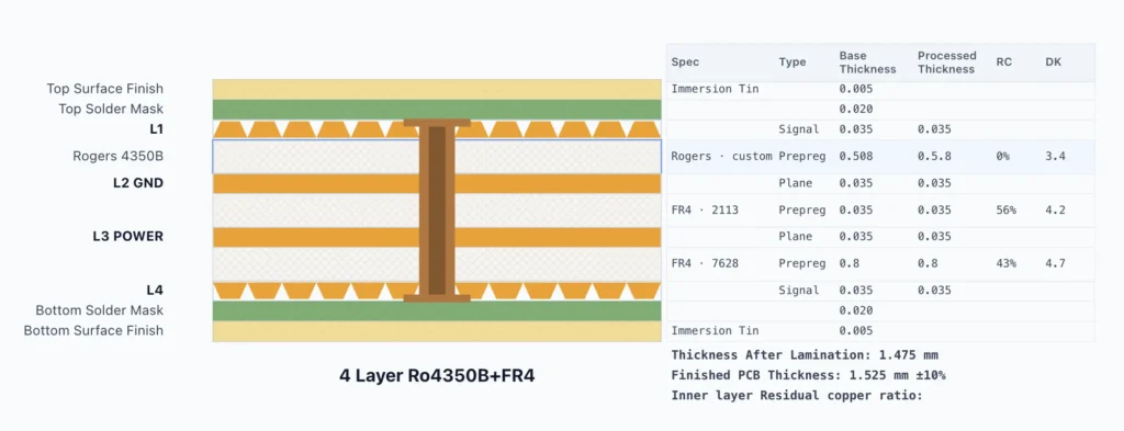
When designing a hybrid stackup, keep the structure symmetric. For example, if RO4350B is used near the top layers, use a similar arrangement near the bottom layers. An unbalanced stackup can increase the risk of warpage after lamination.
Need help optimizing your RO4350B PCB stackup for RF performance, material selection, and production cost?
Rogers 4350B vs FR4
FR4 is affordable, easy to source, and simple to process. It works well for digital signals and low-frequency analog circuits. However, as frequency increases, its higher dielectric loss becomes more noticeable. Above 5–10 GHz, FR4 can start to limit signal performance.
RO4350B is more expensive than FR4. Depending on board size, layer count, and stackup structure, the total board cost can be 5 to 20 times higher. That higher cost brings clear benefits, including stable Dk, low signal loss, and better thermal performance. For RF circuits above a few GHz, these advantages often justify the added cost.
A simple rule can help with material selection. If the circuit transmits or receives RF energy, such as antennas, filters, or power amplifiers, RO4350B is usually the better choice. If the signals remain mainly as digital data on the PCB, FR4 is often more cost-effective.
You also do not need to use RO4350B across the whole board. A hybrid stackup can place RO4350B only on the RF layers, while FR4 is used for digital, control, or power layers. This keeps RF performance where it matters and reduces the total material cost.
Trace width is another practical difference. RO4350B has a lower Dk than FR4, which is often around 4.2–4.5. Because of this, a 50-ohm microstrip trace on RO4350B is usually wider than the same trace on FR4 at the same board thickness. If you move a design from FR4 to RO4350B, do not reuse the old trace widths. Recalculate the impedance before fabrication.
Rogers 4003C vs 4350B
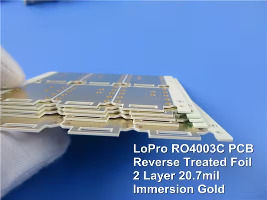
RO4003C is closely related to RO4350B. Both materials belong to the Rogers RO4000 series, and both are used in RF and microwave PCB designs. However, they are not exactly the same.
RO4003C has a slightly lower dielectric constant, usually around 3.38, while RO4350B is around 3.48.
RO4350B has its own advantages. It has a lower Z-axis CTE, which helps improve plated through-hole reliability during thermal cycling. For many general RF applications, RO4350B is the more common choice.
Choose RO4003C when your design needs tighter dielectric control. Precision filters, phase-matched arrays, and circuits with strict phase needs can benefit from its lower Dk. They can also benefit from its tighter tolerance.
If the choice is still unclear, talk to your PCB fabricator early. They can confirm which material is easier to source, which thicknesses are in stock, and which option fits your cost target better.
Which Material Can Replace RO4350B?
RO4350B is widely used in RF and microwave PCB designs, but it is not always the only option. For cost-sensitive projects, you can evaluate some Asian high-frequency laminates as practical alternatives.
LNB33C and S7136H are two Shengyi materials that can be evaluated for RO4350B-type RF PCB designs.
LNB33C is closer to RO4350B from a Dk and Df perspective. For example, LNB33C(350) offers a Dk around 3.50 and a Df around 0.0035, which are close to typical RO4350B values. This makes it a practical option when engineers need a similar dielectric range for impedance-controlled RF circuits.
S7136H is also worth considering because of its material structure and RF application positioning. It is a hydrocarbon-based high-frequency laminate with ceramic filler and glass reinforcement.
Although its Dk may be slightly lower than RO4350B, it is made for RF uses. These include base stations, antennas, power amplifiers, microwave links, and phased-array radar systems.
In general, LNB33C is the closer candidate by electrical values, while S7136H is closer by high-frequency material positioning. Neither should be treated as a direct drop-in replacement for RO4350B. Before production, engineers should recalculate impedance, check insertion loss, and confirm the stackup with the PCB fabricator.
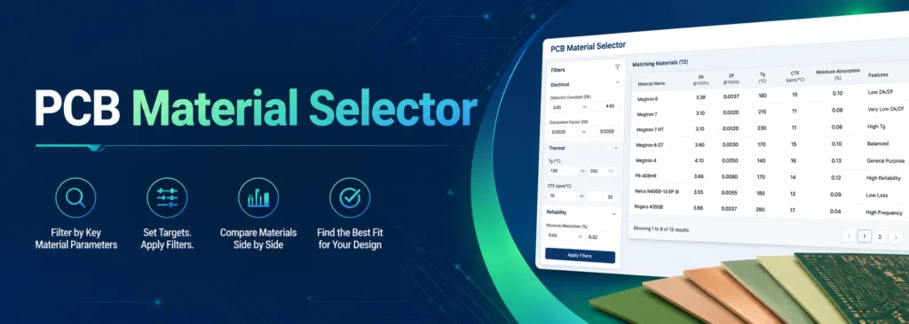
You can use our material selection tool to choose the right laminate for your PCB design.
Conclusion
RO4350B is not always required for the whole board. Many projects can use a hybrid stackup with RO4350B on RF layers and FR4 on digital or power layers.
Before production, engineers should confirm the stackup, copper thickness, bonding material, and material availability with the PCB fabricator.
FAQ