Rogers 3003 PCB Material Guide
Think Deeper with AI:
When your RF design works above 10 GHz, material selection becomes critical. It affects signal loss, and long-term performance.
Rogers 3003 PCB, also known as RO3003, is a proven laminate for these high-frequency applications.
What Is Rogers 3003?
Rogers 3003 is a ceramic-filled PTFE composite laminate developed by Rogers Corporation.
Rogers 3003 belongs to the Rogers RO3000 series, a group of high-frequency circuit materials that includes RO3003, RO3006, RO3010, and RO3035. These materials share similar mechanical properties but provide different dielectric constant (Dk) values for different RF design needs.
The RO3000 Family at a Glance:
| Material | Dk (10 GHz) | Df (10 GHz) | Primary Use Case |
| RO3003 | 3.00 | 0.0010 | 5G mmWave, 77 GHz radar |
| RO3006 | 6.15 | 0.0020 | Compact filters, high-Dk antennas |
| RO3010 | 10.2 | 0.0022 | Miniaturized circuits, patch antennas |
| RO3035 | 3.50 | 0.0015 | Moderate-loss broadband RF |
RO3003 has the lowest Dk and the lowest loss in its family.
This makes it the default choice when signal integrity at millimeter-wave frequencies matters most.
RO3003 is not a general replacement for FR-4. It costs more and needs PTFE processing experience. Use it when signal loss, phase control, or frequency stability drives the design.
Rogers 3003 Data sheet
This datasheet summarizes RO3003 material properties, including Dk, Df, CTE, thermal conductivity, and mechanical reliability for RF PCB design.
| Electrical Properties | Dielectric Constant (Process) | 3.00 ± 0.04 at 10 GHz |
| Dielectric Constant (Design) | 3.16 at 10 GHz | |
| Dissipation Factor | 0.0010 at 10 GHz | |
| Thermal Coefficient of εr | -3 ppm/°C from -50°C to 150°C | |
| Volume Resistivity | 1 × 10⁷ MΩ | |
| Surface Resistivity | 1 × 10⁷ MΩ | |
| Thermal Properties | Thermal Conductivity | 0.50 W/m·K at 50°C |
| X-Axis CTE | 17 ppm/°C | |
| Y-Axis CTE | 16 ppm/°C | |
| Z-Axis CTE | 25 ppm/°C | |
| Lead-Free Process Compatible | Yes | |
| Flammability Rating | UL94 V-0 | |
| Mechanical Properties | Water Absorption | 0.04% |
| Peel Strength | 12.7 lb/in. (2.2 N/mm) | |
| Density | 2.1 g/cm³ | |
| Material Type | Ceramic-filled PTFE composite |
You can use our PCB material tool to compare RO3003 with other Rogers materials. It helps you evaluate Dk, Df, CTE, and application requirements more clearly.
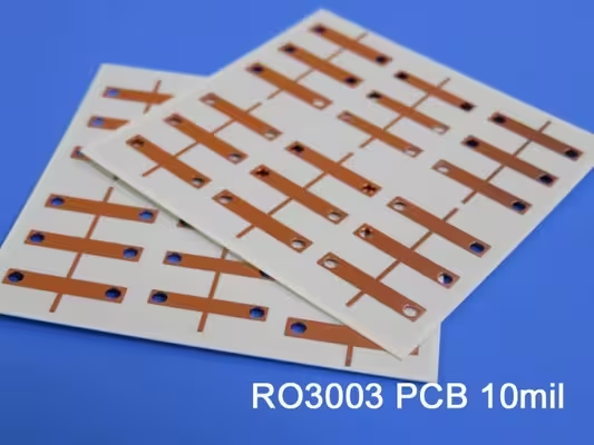
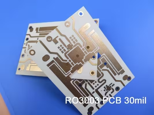
RO3003 PCB Products
Explore our RO3003 PCB products designed for high-frequency applications, including RF, microwave, and radar systems.
Need more details about RO3003? Contact us for datasheet support and PCB material selection guidance.
RO3003G2: The Next-Generation Upgrade
Rogers developed RO3003G2 as an upgraded version of the original RO3003 material platform. It mainly targets next-generation 77 GHz automotive radar designs.
If you are selecting materials for a new mmWave radar project, RO3003G2 should be reviewed early. It offers lower loss, better Dk control, and smoother copper options for fine RF structures.
What Makes RO3003G2 Different?
Lower insertion loss
RO3003G2 provides lower insertion loss than standard RO3003 in 77 GHz applications. For 5 mil material, Rogers lists about 1.3 dB/inch insertion loss using the microstrip differential phase length method. Standard RO3003 is typically higher under similar conditions.
Tighter Dk control
RO3003G2 uses an optimized resin and filler system. This helps reduce Dk variation within the same panel and between different production lots. Better Dk control supports tighter impedance tolerance and improves first-pass yield.
Ultra-low profile ED copper
RO3003G2 uses very low-profile electrodeposited copper. The smoother copper surface helps reduce conductor loss, which is especially important at 77 GHz. At millimeter-wave frequencies, copper roughness can contribute to insertion loss as much as dielectric loss.
9 micron foil option
Rogers also offers RO3003G2 with 9 micron HVLP foil. This thinner copper option helps PCB manufacturers create finer signal lines and antenna patterns. Compact mmWave radar layouts with tight feature control benefit from it.
G2 Specifications Summary
| Parameter | RO3003 | RO3003G2 |
| Dk at 10 GHz | 3.00 ± 0.04 | 3.00 |
| Insertion Loss (5 mil) | ~1.6–1.8 dB/in | 1.3 dB/in |
| Copper Foil Standard | ED (standard profile) | VLP ED |
| Primary Target | General mmWave RF | 77 GHz automotive radar |
Should You Upgrade to G2?
If you are designing a new 77 GHz ADAS radar sensor, RO3003G2 is worth early evaluation. This includes radar systems for adaptive cruise control, forward collision warning, and automated emergency braking.
Its lower loss and tighter material control can support better signal sensitivity and detection performance. These gains are especially useful in compact mmWave radar modules, where every part of the loss budget matters.
RO3003G2 also follows a similar fabrication flow to standard RO3003. This can make material qualification easier for PCB manufacturers that already process RO3003 successfully.
For designs below 40 GHz, standard RO3003 may still be the better choice. If the original RO3003 already meets the link budget, the added cost of RO3003G2 may not bring enough value. In many RF designs, standard RO3003 still provides the right balance of performance, cost, and availability.
Rogers 3003 PCB Cost in 2026
RO3003 PCBs cost more than FR-4 and more than RO4000 series boards. Understanding the cost drivers helps you optimize without compromising RF performance.
Cost Drivers
Material cost: Compared with FR-4 and RO4350B, RO3003 is a higher-cost laminate. Its PTFE-ceramic structure and strict process control contribute to its premium pricing, especially for RF and mmWave applications.
Processing cost: PTFE fabrication usually costs more than RO4000 processing. It may require plasma treatment, slower drilling, more frequent tool changes, and additional inspection. These steps increase machine time and process control requirements. As a result, many PCB manufacturers may charge about 30–60% more than an equivalent RO4000 design.
Prototype vs. production: RO3003 prototype pricing is usually high for small runs, such as 5 to 25 boards. The setup cost is spread across a small quantity. This may include plasma process setup, impedance coupon checks, TDR testing, and extra engineering review.
Production pricing becomes more reasonable when order volume increases. Larger builds allow the factory to spread setup costs across more boards. Using the same RO3003 thickness and copper type across projects can also reduce material purchasing cost.
Cost Reduction Strategies
You don’t have to pay full monolithic RO3003 pricing across the entire board. Effective strategies:
Hybrid stackup: Use RO3003 only for the outer RF signal layers; use FR-4 for inner power/ground/digital layers. This is the most impactful single cost reduction for multilayer RF boards.
Right-size material selection: Don’t specify RO3003 when RO4350B meets your loss and frequency requirements. If your design tops out at 15 GHz and Df of 0.004 closes your link budget, RO4350B saves 30–40% on material cost.
Lead Times in 2026
Material availability matters: RO3003 in standard thicknesses (10 mil, 20 mil) is stocked by most RF-capable fabs. Less common thicknesses, such as 5 mil or 60 mil, may need 2–6 weeks for material sourcing if they are not in stock. Always confirm stock availability before finalizing your thickness selection.
Standard prototype lead time: 10–15 business days for 2-layer at stocked fabs; 15–20 days for multilayer hybrid.
Rush options: Some fabs offer 7–10 day turnaround for standard 2-layer RO3003 at a 30–50% premium.
Conclusion
RO3003 PCB is widely used as a standard laminate for commercial RF designs operating from 10 GHz up to 77 GHz and beyond. It delivers low loss (Df 0.0010 at 10 GHz), stable Dk of 3.00 ± 0.04, and copper-matched CTE for RF and mmWave PCB applications.
Material selection guidelines:
| Frequency / Requirement | Recommended Material |
|---|---|
| Below 20 GHz, cost-sensitive | RO4350B |
| 20–77 GHz commercial RF | RO3003 |
| New 77 GHz automotive radar (ADAS) | RO3003G2 |
| Space, military, or ultra-low-loss | RT/duroid 5880 |
When sourcing RO3003 PCBs, you should ensure the fabricator has plasma treatment capability, stable laminate thickness availability, and TDR impedance testing as part of its standard process.
These factors are key indicators of whether a manufacturer can reliably process RO3003 for high-frequency applications.
Looking for RO3003 PCB manufacturing? Contact our engineering team for stackup design support, material comparison, and a fast quote.
FAQ