Rogers 5880 PCB Manufacturing Guide
Think Deeper with AI:
What Is Rogers RT/Duroid 5880?
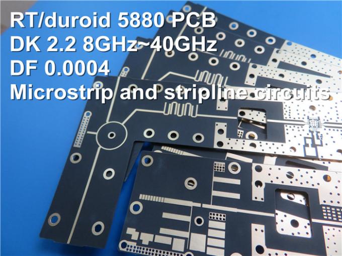
Rogers RT/duroid 5880, also known as Rogers 5880, is a high-frequency PCB laminate for RF and microwave circuits. Rogers 5880 is made from PTFE material reinforced with randomly oriented glass microfibers. This material offers a low dielectric constant and very low signal loss. It also supports stable performance across a wide frequency range.
Compared with RO4350B and RO4003C, Rogers 5880 uses a different material system. RO4350B and RO4003C are hydrocarbon ceramic laminates, while Rogers 5880 is a PTFE composite laminate. This difference affects not only electrical performance, but also drilling, bonding, lamination, via reliability, and total PCB manufacturing cost.
Rogers 5880 is a premium low-loss PCB material. Engineers often use it when RO4350B or RO4003C cannot meet the loss target. It costs more, but it is a strong choice for low loss, stable Dk, phase control, and wideband RF performance.
Why Rogers 5880 Has Ultra-Low Loss
Dk = 2.20 ± 0.02 at 10 GHz
The dielectric constant of Rogers 5880 is 2.20 ± 0.02 at 10 GHz. This low Dk is one of its most important features.
A lower Dk means the signal travels through the material with less delay compared with higher-Dk materials. It also allows wider trace widths for a target impedance, such as 50Ω microstrip. Wider traces can reduce conductor loss, but they also need more board space.
For antenna design, a stable Dk supports predictable frequency response. Small Dk changes can shift antenna behavior, especially at microwave and mmWave frequencies. This is why Rogers 5880 is often used in antenna arrays, radar boards, and broadband RF structures.
However, low Dk does not mean the material is always the best choice. If your board has limited space or needs smaller RF structures, a higher-Dk material such as RO3003 may fit better.
Df = 0.0009 at 10 GHz
The dissipation factor of Rogers 5880 is about 0.0009 at 10 GHz. This low Df means the material absorbs less signal energy as heat.
For RF designers, this matters because dielectric loss becomes more serious as frequency rises. A material that works well at 2 GHz may create too much loss at 28 GHz or 77 GHz.
Engineers often choose Rogers 5880 when the signal path cannot tolerate high insertion loss. Examples include satellite communication, radar front ends, precision RF test boards, and high-efficiency antennas.
Wide Frequency Stability From 1 GHz to 110 GHz
Rogers 5880 offers stable electrical behavior across a broad frequency range. This is one reason engineers use it in broadband and mmWave circuits.
For wideband systems, stable Dk matters as much as low Df. If Dk changes too much with frequency, impedance, and antenna behavior can shift. This makes simulation less reliable.
Low Moisture Absorption: 0.02%
Rogers 5880 has low moisture absorption, about 0.02%. This keep RF performance stable in humid or outdoor environments.
Moisture can change dielectric behavior. It can also affect long-term reliability. For communication equipment, satellite systems, radar, and outdoor RF modules, low moisture absorption reduces risk.
This does not mean the PCB can ignore coating, sealing, or environmental protection. The full product design still needs moisture control.
Design Dk vs Process Dk
People mainly use Process Dk for material control. It helps define the laminate under a test method. Design Dk is more useful for circuit design, impedance calculation, and simulation.
When you design a real PCB, the final impedance depends on more than laminate Dk. It also depends on copper thickness, copper roughness, dielectric thickness, trace width, solder mask, etching tolerance, and fabrication control.
This is why you should confirm the stackup with the PCB manufacturer before layout.
You should review the Rogers 5880 thickness, copper type, and impedance target together.
Need custom Rogers 5880 PCB? Send us your stackup and Gerber files for material review, manufacturing advice, and a fast quote.
RT/duroid 5880 vs Competing Materials
Rogers 5880 vs RO4350B
RO4350B is a popular high-frequency laminate for commercial RF boards. It offers better RF performance than FR4 and easier processing than PTFE-based materials.
Rogers 5880 offers lower loss than RO4350B, but it also brings higher material cost and more demanding fabrication steps.
Choose RO4350B when the design needs solid RF performance, volume production, and easier manufacturing. Choose Rogers 5880 when the design needs ultra-low loss, wideband stability, and strong performance above 10 GHz.
A common mistake is using Rogers 5880 for a board that RO4350B can handle. This adds cost and lead time without a clear performance gain.
Rogers 5880 vs RO3003
RO3003 is another low-loss Rogers material. It has a higher Dk than Rogers 5880, usually around 3.00. This makes RF traces and antenna structures smaller compared with Rogers 5880.
RO3003 is common in 77 GHz automotive radar, mmWave systems, and compact RF modules. Rogers 5880 works well when a low Dk and low loss are both important.
When comparing Rogers 5880 and RO3003, Df should not be the only selection factor. Compare frequency, circuit size, antenna behavior, stackup, copper foil, fabrication yield, and total cost.
Rogers 5880 vs RT/duroid 5870
RT/duroid 5870 is close to Rogers 5880 in material family and use case. Both are PTFE-based laminates for microwave and RF circuits.
The main difference is Dk. RT/duroid 5870 has a higher Dk than Rogers 5880. This may allow smaller circuit structures while still keeping low loss.
If your design needs the lowest Dk in this material family, Rogers 5880 may be the better option. If your design needs smaller RF geometry, RT/duroid 5870 may deserve review.
To compare more material data, use our online PCB material selector.
Limitations of RT/duroid 5880
High Z-Axis CTE and Via Reliability Risk
Rogers 5880 has a high Z-axis CTE compared with many standard PCB materials. A high Z-axis CTE means the material expands more through the board thickness during heat cycles.
This creates stress around plated through holes. The risk increases in thick boards, multilayer boards, and boards that pass through lead-free assembly.
For simple 2-layer RF boards, this may not be a major issue. For multilayer RF boards with many vias, it needs careful review.
Low Thermal Conductivity and Power Amplifier Design
Rogers 5880 is a low-loss dielectric, but it is not a thermal management material. Its thermal conductivity is limited compared with metal-backed boards or special thermal substrates.
This matters in power amplifiers, high-power RF circuits, and compact modules. Heat can shift RF behavior and reduce reliability.
If your board includes power devices, do not focus only on Dk and Df. Review copper area, thermal vias, heat spreaders, metal housing contact, and assembly method. The RF material must work with the full thermal path.
Soft Material and Mechanical Assembly Notes
Rogers 5880 is softer than standard FR4. This helps its RF behavior, but it also means the board needs better handling during fabrication and assembly.
Mechanical stress, over-tightened screws, poor fixture design, and repeated rework can damage the board or affect reliability.
For products that need strong mechanical support, use careful housing design. Avoid making the laminate carry all mechanical stress.
Rogers 5880 PCB Manufacturing Considerations
PTFE Low Surface Energy and Plasma Treatment
Rogers 5880 uses a PTFE-based system. PTFE has low surface energy, so bonding and plating require more care than standard FR4.
Before plating or bonding, the material surface often needs special preparation. Plasma treatment or chemical treatment can improve surface activation and hole wall condition.
If a factory lacks PTFE process experience, the board may face weak copper bonding, poor hole wall quality, or low yield. This risk may not show during quotation, but it can appear during production.
The surface energy of PTFE-based material is low. For this reason, fabrication control matters as much as material selection.
Drilling Parameter Control
Drilling Rogers 5880 requires controlled speed, feed rate, drill quality, and cleaning steps. Poor drilling can cause rough hole walls, smear, or weak plating.
For RF boards, drilling quality also affects signal performance. Vias in RF paths can create impedance discontinuities. The drill size, pad size, anti-pad size, and via location should match the RF design.
Do not treat vias as simple connections in a high-frequency board. At microwave frequency, every transition becomes part of the RF structure.
Copper Foil Selection: ED vs Rolled Copper
Copper foil affects insertion loss. At high frequency, current flows near the copper surface. A rougher copper surface can increase conductor loss.
ED copper is common and cost-effective. Rolled copper can offer smoother surface behavior in some RF cases, but cost and availability may differ.
For Rogers 5880 PCB, confirm the copper foil type before layout. The same material name with different copper foil can lead to different loss results.
If the project has a strict loss budget, you should ask the PCB manufacturer about copper roughness, copper weight, and available foil options.
Multilayer Lamination
Multilayer Rogers 5880 boards need careful lamination control. PTFE materials behave differently from FR4 during pressure and heat cycles.
Key risks include layer shift, bonding issues, voids, warpage, and via reliability problems. These risks grow as layer count increases.
If your design needs many layers, ask the factory to review the stackup early. The review should include bonding material, lamination cycle, hole structure, board thickness, and panel size.
Hybrid Stackup: 5880 + FR4 or RO4003C
A hybrid stackup can reduce cost. In this structure, Rogers 5880 is used only on RF signal layers. FR4 or RO4003C can support digital, power, or control layers.
This is often a better choice for mixed-signal systems. Many boards do not need ultra-low-loss material on every layer.
A good hybrid design starts with clear layer function. Use Rogers 5880 where RF loss matters. Use lower-cost materials where RF performance does not drive the design.
However, hybrid lamination needs review. Different materials expand and bond in different ways. The PCB factory must check CTE, bonding film, lamination process, and warpage risk.
When Rogers 5880 May Not Be the Right Choice
Rogers 5880 is an excellent RF material, but it is not right for every RF board.
Avoid Rogers 5880 when the working frequency is below 6 GHz and the loss target is moderate.
In many standard RF designs, RO4350B or RO4003C can provide enough performance with lower cost and easier production.
For cost-sensitive commercial products, Rogers 5880 may push the budget too high. Material cost, PTFE processing, yield control, and longer lead time all affect the final price.
It may also be a poor fit for complex multilayer boards with many layers. PTFE fabrication becomes harder as the stackup becomes more complex. The yield risk can rise fast if the factory lacks experience.
Rogers 5880 may also be less suitable when the product needs high mechanical strength. The material is softer than FR4 and needs better mechanical support.
How to Reduce Rogers 5880 PCB Cost
When Should You Choose Rogers 5880?
The first cost-saving step is material review.
If your working frequency is below 10 GHz, review Rogers 4350B first. It has higher loss than Rogers 5880, but it is easier to process and often costs less.
If your frequency is between 10 GHz and 20 GHz, and your loss target is not extreme, review RO4003C or RO4350B. In some cases, these materials can meet the electrical target with lower cost.
Use Standard Rogers 5880 Thickness When Possible
Rogers 5880 thickness options range from thin laminates to thick boards. Common thicknesses include 0.127 mm, 0.254 mm, 0.508 mm, 0.787 mm, 1.575 mm, and 3.175 mm.
Non-standard thickness can increase lead time and cost. It may also require special material ordering.
When possible, choose a standard rogers 5880 thickness that meets impedance and mechanical needs. This helps reduce material lead time and improves quotation stability.
Conclusion
Rogers 5880 is a premium low-loss PCB material for RF, microwave, radar, satellite, broadband, and antenna applications.
But Rogers 5880 is not always the best business choice. For many RF boards below 10 GHz, RO4350B or RO4003C may be enough. For mixed-signal systems, a Rogers 5880 + FR4 hybrid PCB can keep low-loss material on RF layers while reducing total cost.
Before you choose Rogers substrate 5880, review your frequency, thickness, copper foil, stackup, vias, and process capability with your PCB manufacturer.
FAQ
Frequently Asked Questions About Rogers 5880
What is Rogers 5880 PCB used for?
Its low Dk and low Df help reduce signal loss and support stable impedance. Use RT/duroid 5880 when FR4 cannot meet the loss target at high frequency.
What is the dielectric constant of Rogers 5880?
Is Rogers 5880 suitable for 5G mmWave antenna design?
Why is Rogers 5880 PCB more expensive than standard PCB materials?
Drilling, plating, etching, lamination, impedance control, and RF testing can all increase cost. It is worth using only when low-loss performance justifies the budget.