Copper Clad Laminate: A Practical Guide for PCB Design
 steve ran
June 30, 2026
steve ran
June 30, 2026
Think Deeper with AI:


Copper ClaCopper Clad Laminate, also called CCL, is the base material used to manufacture printed circuit boards.
It affects PCB signal performance, thermal behavior, copper adhesion, drilling quality, dimensional stability, and final board cost. Choosing the right CCL is important for both PCB design and long-term reliability.
This guide explains how to select the right CCL for common PCB applications and design requirements.
What Is Copper Clad Laminate?
Copper Clad Laminate (CCL) is a flat base material used to manufacture printed circuit boards. It consists of a copper foil layer bonded to one or both sides of an insulating substrate.
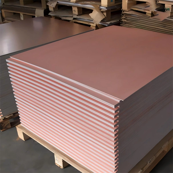
The substrate is typically made from glass fiber cloth and resin. The most common type is FR-4. Other materials are also used for specific applications. These include polyimide, ceramic-filled resins, PTFE, and metal-core structures.
During PCB fabrication, manufacturers do not use copper as a full sheet. Instead, an etching process removes unwanted areas and leaves the circuit patterns, like traces, pads, and planes.
A basic CCL structure includes:
- Top copper foil
- Resin system
- Glass fiber reinforcement
- Bottom copper foil
Some CCLs have copper on only one side, while most rigid PCBs use double-sided copper.
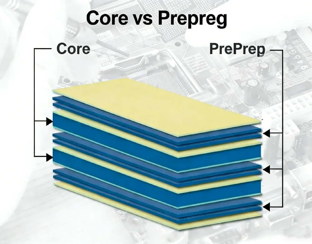
For multilayer boards, multiple copper-clad cores, prepreg layers, and copper foils are stacked.
Then, heat and pressure laminate them to form the final structure.
Standard Sheet Thicknesses and Copper Weights
Copper clad laminate does not have a single standard thickness. Available thicknesses vary by material and manufacturer. You should specify whether the required thickness is measured over the dielectric or over the copper, as IPC-4101 permits both.
For example, Isola’s 370HR FR-4 laminate is available from 2 to 125 mil (0.05–3.2 mm). Standard copper weights include 1/2, 1, and 2 oz, with additional copper weights available on request.
CEM laminates generally have a more limited range of standard constructions than FR-4. For example, Nan Ya’s CEM-3-10 is offered in 0.8, 1.0, 1.2, 1.5, and 1.6 mm thicknesses with 18 or 35 µm copper. Since available constructions vary by manufacturer, buyers should specify the exact product grade instead of ordering only by the generic name CEM-3.
How Copper Clad Laminate Fits Into PCB Manufacturing
PCB manufacturing starts with material selection. The factory chooses a CCL based on board thickness, copper weight, layer count, thermal and signal needs.
For a simple double-sided PCB, the factory starts with a double-sided Copper Clad Laminate. It drills holes, plates vias, images the pattern, and etches the copper.
For a multilayer PCB, the factory uses inner-layer cores and prepreg. A core typically starts as a thin copper clad laminate, while prepreg acts as the bonding material during lamination. Under heat and pressure, the layers press into one solid board.
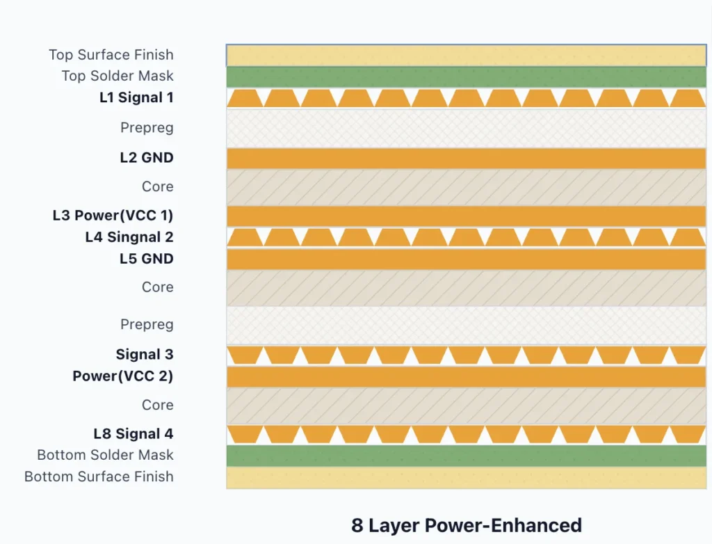
This means the CCL affects many later steps:
- Drilling quality
- Plating reliability
- Soldering behavior
- Board flatness
- Impedance control
- Thermal stress
- Final PCB cost
A poor material choice can create problems that appear much later. The board may pass simple tests but fail in heat, moisture, vibration, or long-term operation.
Main Types of Copper Clad Laminate
Different PCB jobs need different CCL materials. No single material fits every design.
FR-4 Copper Clad Laminate
FR-4 Copper Clad Laminate is the most common PCB material. It uses glass fiber and epoxy resin. It works well for many consumer, industrial, and control boards.
Use FR-4 when the design has normal speed, normal heat, and standard cost needs.
Common uses include:
- Power control boards
- Consumer electronics
- LED control modules
- Industrial sensors
- Basic communication products
FR-4 gives a good balance between price, strength, and process stability.
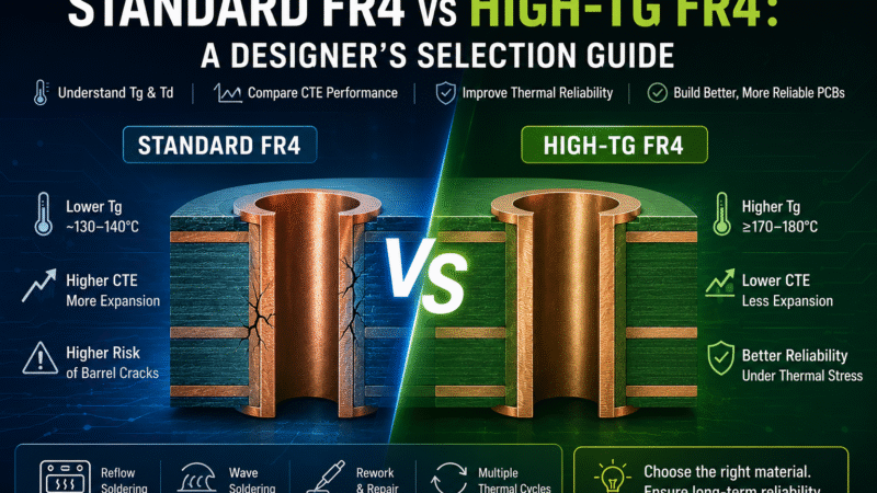
High-Tg Copper Clad Laminate
Tg means glass transition temperature. In simple words, Tg tells you how the board behaves under heat.
A high-Tg CCL handles heat better than standard FR-4. It works well for boards that face lead-free soldering, high operating temperature, or repeated thermal cycles.
Use high-Tg CCL for:
- Automotive electronics
- Industrial control boards
- Power electronics
- Dense multilayer PCBs
- Products with long service life
High-Tg material may cost more, but it can reduce risk during assembly and field use.
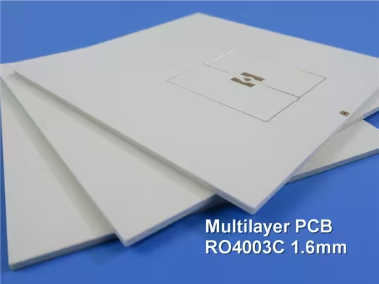
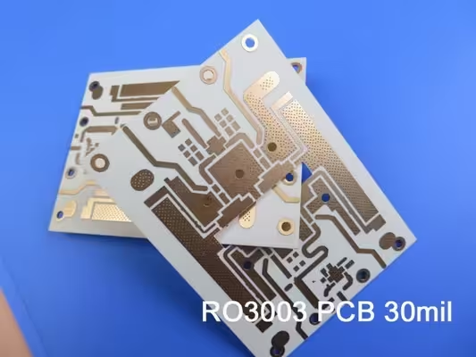
High-Frequency Copper Clad Laminate
High-frequency CCL supports RF, microwave, antenna, radar, and high-speed digital signals.
For these boards, engineers check Dk and Df.
Dk affects signal speed and impedance. Df affects signal loss. Lower and more stable values often help high-frequency designs.
Use high-frequency CCL for:
- RF modules
- Antenna boards
- 5G products
- Radar systems
- High-speed communication boards
- Some AI server and data center boards
Standard FR-4 may work for some high-speed designs. But it can create more loss at higher frequencies.
Metal-Core Copper Clad Laminate
Metal-core CCL uses a metal base, often aluminum. It helps move heat away from hot parts.
Use metal-core CCL for:
- LED lighting
- Power modules
- Motor control
- Automotive lighting
- Heat-heavy products
This material does not behave like normal FR-4. The PCB stack-up, insulation layer, and heat path need careful review.
Flexible Copper Clad Laminate
Flexible Copper Clad Laminate often uses polyimide film and copper foil. It bends without breaking under normal use.
Use flexible CCL for:
- Flex circuits
- Wearable electronics
- Camera modules
- Foldable products
- Tight-space connections
Flex CCL needs different design rules. Bend radius, copper type, adhesive, and coverlay all matter.
FR-4, CEM-1, CEM-3, FCCL, PTFE, and Aluminum CCL Comparison
Material names define material families, not fixed performance levels. FR-4, CEM, FCCL, PTFE, and metal-base laminates are available in different grades with different properties. Use this table for a general comparison, then confirm the product data sheet before making a final selection.
| Material family | Typical construction | Main strengths | Main limitations or checks | Common application fit |
| FR‑4 CCL | Epoxy laminate reinforced with woven E-glass and clad with copper. | Broad availability; suitable for rigid single-, double-, and multilayer PCBs; available in many performance grades. | “FR‑4” alone does not define Tg, Dk/Df, CAF performance, or lead‑free assembly capability | Industrial controls, computing, communications, automotive‑qualified designs, and general multilayer PCBs |
| CEM‑1 | Woven glass fabric surfaces with a cellulose‑paper core in an epoxy system; commonly supplied as single‑sided CCL | Lower‑cost construction with good punching and drilling characteristics | Usually not the first choice for demanding multilayer, high‑speed, or repeated high‑temperature assembly; confirm PTH and process requirements | Cost‑sensitive single‑sided power boards, controls, appliances, and general electronics |
| CEM‑3 | Woven glass fabric surfaces with a glass nonwoven core in epoxy resin | Better fit than CEM‑1 for double‑sided constructions; good punching and drilling; high‑CTI grades are available | Properties vary by grade; confirm dimensional stability, thermal endurance, PTH reliability, and copper options | Cost‑sensitive double‑sided boards, power supplies, appliances, displays, controls, and selected automotive electronics |
| FCCL | Copper foil bonded to a flexible film, often polyimide; available with adhesive or as a two‑layer adhesiveless construction | Thin, lightweight, bendable, and suitable for three‑dimensional packaging; specialized low‑loss grades are available | Dynamic‑flex life depends on the full construction, copper type, bend radius, grain direction, and processing; rigid‑board thickness rules do not apply | Flex circuits, cameras, displays, battery modules, medical devices, cables, automotive modules, and compact electronics |
| PTFE‑based CCL | PTFE resin with woven or nonwoven glass and, in some grades, ceramic filler | Low dielectric loss and stable RF performance across broad frequency ranges; suitable for controlled microwave behavior | Requires material‑specific fabrication controls; Dk, CTE, copper profile, and reinforcement must match the RF design | Antennas, radar, satellite, microwave, RF power amplifiers, and 5G infrastructure |
| Aluminum CCL | Copper circuit layer, thermally conductive dielectric, and aluminum base plate | Transfers heat toward the metal base while maintaining electrical insulation; mechanically robust | Stack‑up options are product‑specific; dielectric thickness, breakdown voltage, and thermal impedance require careful review | LED lighting, power conversion, motor drives, automotive lighting, and other heat‑producing electronics |
Copper weight conversion
Copper foil is commonly specified in ounces per square foot (oz/ft²). This value describes the copper weight per unit area, not the total weight of the sheet.
| Copper weight | Nominal foil thickness | Typical use in a material order |
| 1/4 oz | 9 µm | Ultra-thin starting copper for fine features; limited to selected products |
| 1/2 oz | 18 µm | Thin starting copper and many high-frequency laminates |
| 1 oz | 35 µm | Common rigid CCL construction |
| 2 oz | 70 µm | Higher current or improved heat spreading |
| 3 oz | 105 µm | Heavy-copper products; supplier-specific availability |
| 4 oz | 140 µm | Heavy-copper and selected metal-base products |
These conversions follow Rogers’ copper foil guide, where 1/4, 1/2, 1, 2, 3, and 4 oz copper correspond to nominal thicknesses of 9, 18, 35, 70, 105, and 140 µm. Not every laminate is available with every copper weight.
The specified foil weight is not always the same as the finished copper thickness. During PCB fabrication, outer layers gain additional copper through electroplating. Foil profile and surface treatment also influence conductor loss, adhesion, and high-frequency performance. For controlled-impedance or RF designs, specify both the copper weight and foil type, such as rolled annealed (RA), electrodeposited (ED), reverse-treated (RTF), or low-profile (LP) copper.
Flexible and metal-base laminates require different specifications. FCCL is typically defined by the copper foil, base film (such as polyimide), adhesive system, and individual layer thicknesses. Aluminum CCL is specified by copper weight, dielectric thickness, and aluminum base thickness. Using a standard FR-4 sheet description for these materials may result in an inaccurate quotation.
Recommended purchase specification:
- Material grade and revision
- IPC specification or IPC-4101 slash sheet
- Dielectric thickness (and total laminate thickness if required)
- Copper type and copper weight for each side
- Panel size and thickness tolerance
- Surface quality or inspection class
- UL file number or required compliance
- Special electrical or thermal requirements, such as controlled impedance or thermal conductivity
Key CCL Properties That Affect PCB Performance
When engineers choose Copper Clad Laminate, they should not look only at price. The key material properties tell you how the board will perform.
| Property | What It Means | Why It Matters | Common Values / Key Points | Best Used For |
|---|---|---|---|---|
| Copper Thickness | The thickness or weight of the copper layer on the CCL. | It affects current flow, heat spreading, etching quality, and trace width. | Common copper weights include 0.5 oz, 1 oz, 2 oz, 3 oz, and heavy copper options. Thicker copper carries more current and spreads heat better, but it costs more and needs wider spacing during etching. | 1 oz often works for signal boards. 2 oz or more is common for power boards. |
| Tg | Glass transition temperature. It shows how the base material responds to heat. | When the board gets close to or above Tg, the material expands more. This can stress vias, pads, and inner layers. | Higher Tg is better for heat stress and long-term reliability. | Lead-free soldering, high operating temperature, dense multilayer stack-ups, automotive use, and harsh field conditions. |
| Dk and Df | Dk means dielectric constant. Df means dissipation factor. | Dk affects impedance and signal speed. Df affects signal loss. If these values change too much with frequency or temperature, signals may become less stable. | These values matter most for high-speed and high-frequency boards. For simple control boards, they may not drive the choice. | RF boards, high-speed digital boards, antennas, communication boards, and fast signal designs. |
| CTE | Coefficient of thermal expansion. It shows how much the material grows when heated. | Copper, resin, and glass expand at different rates. This mismatch can create stress during soldering or field use. | High CTE can raise the risk of via cracks, pad lifting, delamination, barrel failure, and board warpage. | Boards exposed to heat cycling, soldering stress, automotive use, and high-reliability applications. |
| Peel Strength | How well the copper sticks to the base material. | Strong peel strength keeps copper bonded during etching, soldering, rework, and long use. | Poor peel strength can lead to lifted copper, damaged traces, or weak pads. | Fine traces, heavy copper, high heat, rework needs, and harsh environments. |
| CAF Resistance | Resistance to conductive anodic filament growth inside PCB material. | CAF is a hidden failure path. It can happen when moisture, voltage, and weak glass-resin bonding create a conductive path, causing leakage or shorts. | Higher CAF resistance improves reliability in humid and high-voltage conditions. | High-voltage boards, humid environments, tight spacing, automotive electronics, and industrial products. |
You can use our online PCB Material Selector to compare detailed PCB material data.
Certifications and Test Methods
A reliable CCL specification separates material standards, test methods, safety recognition, regulatory declarations, and management-system certificates. These documents answer different questions and should not be treated as interchangeable.
Standards and compliance documents
| Document or program | What it covers | What the buyer should verify |
|---|---|---|
| IPC‑4101 | Requirements for laminate and prepreg used in rigid and multilayer printed boards | Exact slash sheet, material grade, thickness range, and whether the supplier or product appears on an applicable QPL |
| IPC‑4204 | Flexible metal‑clad dielectrics used to fabricate flexible printed boards | Exact FCCL material type and slash sheet; adhesive and adhesiveless materials do not use identical requirements |
| IPC‑TM‑650 | Test procedures for mechanical, electrical, thermal, and environmental properties | Method number, revision, conditioning, test frequency, specimen thickness, and acceptance limit |
| UL 94 | Flammability classification for plastic materials | The recognized grade and rating, such as V‑0 or VTM‑0, in the supplier’s UL file |
| UL 746E | Industrial laminates and materials used in printed wiring boards | The recognized material designation, color, thickness range, copper construction, and temperature index where applicable |
| IEC 60112 | Proof tracking index and comparative tracking index testing for solid insulating materials | Whether the stated value is CTI or PTI and the tested material/condition |
| RoHS and REACH documentation | Restricted‑substance and chemical‑regulatory compliance | Current declaration date, material grade, applicable exemptions, and supporting analytical report where required |
| ISO 9001 or IATF 16949 | The manufacturer’s quality‑management system | Certified site and scope; these certificates do not prove that a specific laminate meets IPC or UL requirements |
IPC-4101 specifies rigid PCB laminates, and IPC-4204 covers flexible metal-clad dielectrics. UL 746E, UL 94, and IEC 60112 define key requirements for laminate safety, flammability, and electrical tracking performance.
Common CCL tests
| Property | Common test method | Why it matters |
|---|---|---|
| Peel strength of rigid metal‑clad laminate | IPC‑TM‑650 2.4.8 | Measures copper‑to‑dielectric adhesion before or after specified conditioning |
| Peel strength of flexible dielectric material | IPC‑TM‑650 2.4.9 | Evaluates adhesion in FCCL and other flexible constructions |
| Thermal stress / solder float resistance | IPC‑TM‑650 2.4.13 or 2.4.13.1, as specified | Screens for blistering, delamination, and other damage during thermal exposure |
| Glass transition temperature, Tg | IPC‑TM‑650 2.4.25 by DSC; TMA methods may also be specified | Supports material selection for assembly temperature and thermal cycling |
| Z‑axis expansion and time to delamination | IPC‑TM‑650 2.4.24 family | Indicates thermal‑expansion behavior and resistance to delamination at elevated temperature |
| Dielectric constant and dissipation factor | IPC‑TM‑650 2.5.5 method family | Supports impedance and signal‑loss calculations; the method and frequency must accompany the value |
| Dielectric breakdown / electric strength | IPC‑TM‑650 2.5.6 family | Assesses insulation performance under electrical stress |
| Surface and volume resistivity | IPC‑TM‑650 2.5.17 | Evaluates insulating behavior under the stated conditioning |
| Water absorption | IPC‑TM‑650 2.6.2.1 for metal‑clad plastic laminate | Measures water uptake after defined conditioning and immersion |
| CAF resistance | IPC‑TM‑650 2.6.25 | Evaluates conductive anodic filament growth under voltage, temperature, and humidity stress |
| CTI / PTI | IEC 60112 | Compares resistance to surface tracking under wet electrical stress |
| Flammability | UL 94 | Classifies burning behavior under a defined test setup |
IPC publishes the current IPC-TM-650 test-method index, including 2.4.8 for rigid laminate peel strength, 2.4.9 for flexible materials, the 2.5.5 family for Dk/Df, 2.6.2.1 for water absorption, and 2.6.25 for CAF resistance.
The test method number alone does not provide a complete engineering comparison. Test conditions—including conditioning, specimen thickness, copper type, test direction, and test frequency—as well as whether a value is reported as a typical result or a guaranteed specification, can all affect the measured performance.
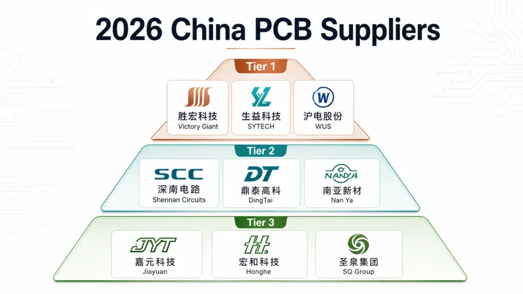
Copper Clad Laminate Manufacturers in China 2026
In 2026, copper foil prices have increased significantly, driven by multiple factors.
Tariff policies have added uncertainty to material imports and the supply chain. The U.S.–Iran conflict has also increased global logistics risks.
However, the more important factor is the rapid growth of AI infrastructure demand. As AI servers, data centers, and high-performance computing equipment grow, the need for high-performance PCBs increases. Demand for copper foil and other copper materials also rises.
Demand is growing quickly, while supply cannot fully keep up in the short term. As a result, copper foil prices have risen sharply. This directly affects the cost of Copper Clad Laminate and PCB manufacturing.
Many PCB manufacturers have reduced or stopped taking low-end board orders. They increasingly focus their production capacity on higher-layer PCBs, high-frequency boards, and other higher-value products.
For PCB buyers, CCL selection is no longer only about price. Material availability, lead time, and supplier capability now play a larger role in PCB project planning.
How HXD Circuit Supports PCB Material Selection
Material choice can slow a project when the design team and factory do not review it early.
A simple board may only need standard FR-4. A high-reliability board needs deeper review.
HXD Circuit can help review key PCB material points before production. These points may include the following checklist:
- Board layer count
- Board thickness
- Copper weight
- Operating temperature
- Assembly temperature
- Current load
- Signal speed
- Impedance needs
- Moisture exposure
- Vibration or shock
- Required lifetime
- Target price
- Lead time
- Supplier process limits
The goal is simple: select a Copper Clad Laminate based on real application needs, not only the lowest price on the quote.
Need reliable PCB materials? Contact HXD Circuit to choose the right Copper Clad Laminate today
Conclusion
In 2026, CCL also links to supply chain risk. AI demand, and raw material pressure can affect cost and lead time. Buyers should plan material choices early and work with suppliers who understand both PCB design and production reality.
HXD Circuit can support this review and help match the PCB material to the product, budget, and delivery plan.