SMT vs THT PCB Assembly
 steve ran
August 11, 2026
steve ran
August 11, 2026
Choosing between SMT and THT assembly affects PCB size, manufacturing cost, and production speed. This guide compares SMT vs THT assembly and explains how engineers and PCB buyers can select the right process.
SMT vs THT Assembly at a Glance
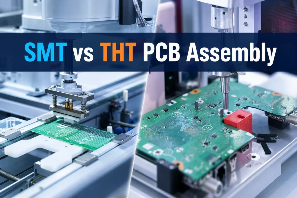
SMT (Surface mount technology) mounts components directly onto PCB pads. THT(Through-hole technology) inserts component leads through plated holes before soldering them on the opposite side.
SMT works well for compact, high-density products and automated production. THT provides strong mechanical support for connectors, switches, transformers, and other stressed components. Many products use both methods to balance size and cost.
| Factor | SMT Assembly | THT Assembly |
|---|---|---|
| Mounting method | Components sit on surface pads | Leads pass through PCB holes |
| Main soldering process | Reflow soldering | Wave, selective, or hand soldering |
| Component density | High | Lower |
| Automation level | High | Moderate or low |
| Mechanical anchoring | Depends on pads and reinforcement | Strong |
| High-frequency performance | Usually better | Longer leads add parasitic effects |
| Assembly speed | Fast at scale | Slower |
| High-volume cost | Usually lower | Usually higher |
| Manual prototyping | More difficult | Easier |
| Typical applications | Compact and high-density electronics | Connectors, switches, and power components |
Each process has its own strengths, so the right choice depends on your product requirements.
Advantages of SMT assembly
SMT supports smaller components and higher placement density. You can place components on both sides of a PCB, reduce board dimensions, and gain more routing space.
Short component connections also reduce parasitic inductance and capacitance. This characteristic makes SMT suitable for RF, high-speed digital, and communication products.
Automated placement provides another advantage. Once the manufacturer finishes stencil setup and machine programming, the line can place thousands of parts fast and consistently.
Limitations of SMT assembly
SMT requires production setup. Stencils, machine programs, feeders, reflow profiles, and inspection programs add initial costs. These costs have a larger effect on small prototype orders.
Small components also require specialized rework skills. Technicians may need hot-air tools, microscopes, preheaters, or BGA rework equipment.
Mechanical strength depends on component design and PCB support. Surface-mounted connectors or heavy parts may need mounting tabs, adhesive, or enclosure support to prevent pad damage.
Advantages of THT assembly
The component leads create strong mechanical anchoring. This structure suits components exposed to cable pull, repeated mating, vibration, or user operation.
Technicians can also inspect and replace many THT components with standard soldering tools. This feature supports laboratory prototypes, educational projects, and serviceable industrial equipment.
THT remains useful for heavy components and packages that have no practical SMT replacement.
Limitations of THT assembly
Every THT lead needs a drilled hole. Those holes consume board area and restrict routing through multiple layers. The result may require a larger PCB or a more complex layout.
THT assembly also involves more handling. Lead forming, component insertion, soldering, trimming, and inspection can increase labor and cycle time.
These factors often make THT more expensive for medium- and high-volume production.
Detailed SMT vs THT Comparison
PCB size and component density
SMT offers the clearest advantage when space matters. Small packages and double-sided placement allow designers to fit more functions into a smaller PCB.
THT components need larger pads, drilled holes, and extra spacing. Their leads also occupy routing space on internal layers.
Wearable devices, IoT products, smartphones, and compact controllers therefore rely heavily on SMT.
Mechanical strength
THT provides strong support when a component faces direct mechanical force. Connectors, terminal blocks, and switches often benefit from leads that pass through the PCB.
However, THT does not automatically make an entire assembly more reliable. A lightweight SMT resistor may withstand vibration better than a heavy THT component with poor support.
Engineers should evaluate component mass, board flex, mounting method, vibration frequency, and enclosure support. Reinforced SMT connectors can perform well when their mounting tabs and PCB pads suit the expected load.
Electrical performance
SMT usually provides better high-frequency performance. Short terminals reduce unwanted inductance and capacitance. Designers can also place components closer to IC pins and shorten critical signal paths.
THT leads create longer current paths. Plated holes may form signal stubs in high-speed designs. These effects can degrade signal integrity when frequencies increase.
The complete PCB stack-up and routing strategy still matter more than package style alone.
Thermal and power performance
Package selection, copper area, thermal vias, airflow, and heatsinks determine thermal performance. Both technologies can support power applications when engineers design the thermal path correctly.
Large transformers, relays, and power components often use THT because of their weight and lead structure. Modern SMT power packages can also handle substantial current when connected to suitable copper planes and thermal vias.
Repair and rework
THT components usually offer easier access for manual replacement. Technicians can identify leads, remove solder, and install new parts with common tools.
SMT rework becomes harder as package size and pin density increase. Replacing a 0603 resistor is simple for an experienced technician. Replacing a BGA needs controlled heating and X-ray checks.
Production scalability
SMT provides strong scalability. Automated printing, placement, reflow, and inspection support consistent production across medium and large orders.
THT throughput depends on component type and insertion method. Manual insertion limits production speed. Selective soldering improves consistency but adds programming and fixture requirements.
SMT vs THT Assembly Cost
SMT does not always cost less, and THT does not always cost more. Order quantity, component mix, inspection needs, and process complexity determine the final price.
SMT cost factors
SMT setup may include:
- Stencil manufacturing
- Pick-and-place programming
- Feeder preparation
- Reflow profile development
- AOI and X-ray programming
These charges can make a small prototype order appear expensive. Unit cost normally falls as the order quantity increases because automation spreads setup expenses across more boards.
THT cost factors
THT costs may include:
- Additional PCB drilling
- Component lead forming
- Manual insertion
- Wave or selective solder fixtures
- Hand-soldering labor
- Lead trimming and cleaning
A board with only two THT connectors may add little cost. A board with dozens of manually inserted components can require substantial labor.
Hidden costs
Buyers should also consider:
- Larger PCB dimensions
- Additional process passes
- Component packaging
- Complex rework
- Custom fixtures
- Inspection requirements
- Low-yield fine-pitch assembly
- Component substitutions
The lowest assembly price may not produce the lowest total product cost. A more compact SMT design may reduce PCB material and enclosure costs. A THT connector may prevent field failures and warranty expenses.
When Should You Choose SMT?
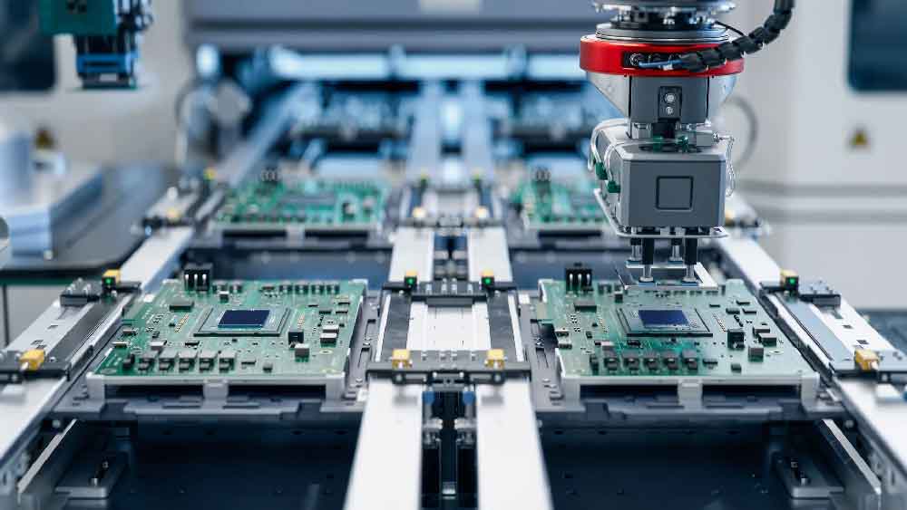
Choose SMT assembly when the product requires:
- A compact or lightweight PCB
- High component density
- Double-sided component placement
- High-speed or RF performance
- Automated medium- or high-volume production
- Modern IC packages such as QFN or BGA
Consumer electronics, IoT devices, communication systems, and compact control boards commonly use SMT.
When Should You Choose THT?
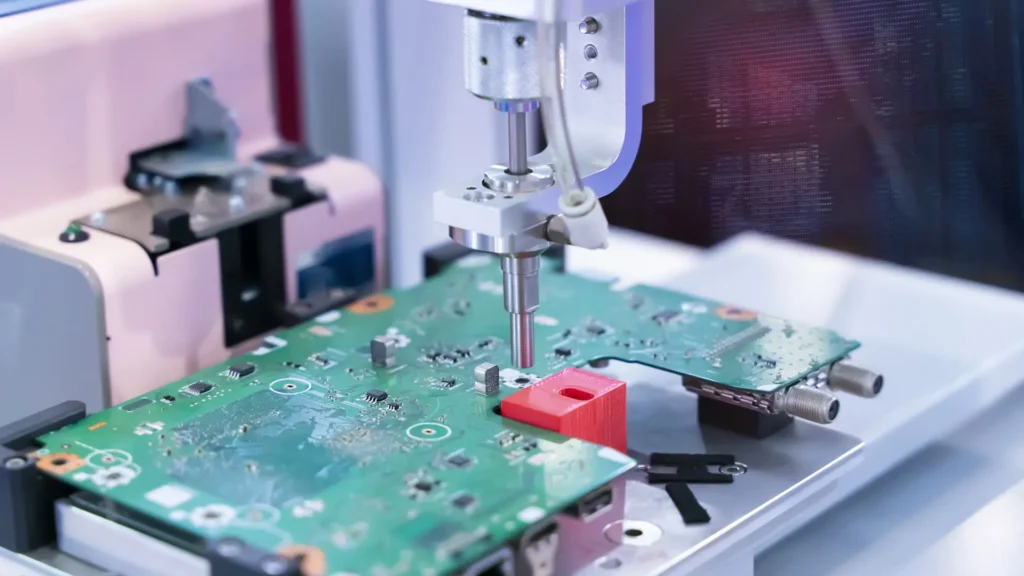
Choose THT assembly when the product includes:
- Frequently mated connectors
- Terminal blocks exposed to cable force
- User-operated switches
- Heavy transformers or relays
- Large power components
- Parts that require frequent manual replacement
THT can also suit early laboratory prototypes when engineers need to replace components repeatedly.
When Is Mixed Assembly Better?
Many commercial PCBAs combine SMT and THT components.
A mixed board may use SMT resistors, capacitors, ICs, and sensors while retaining THT connectors, relays, and transformers. This approach provides SMT density and automation without sacrificing mechanical support where the product needs it.
A typical process follows this sequence:
- Solder Paste Printing
- SMT Placement
- Reflow Soldering
- AOI and X-ray Inspection
- THT Component Insertion
- Wave, Selective, or Hand Soldering
- Final Inspection
- Electrical and Functional Testing
Need PCBA Manufacturing Support?
Send your Gerber files and BOM to HXD Circuit. Our team provides DFM review, component sourcing, SMT and THT assembly,and production support from prototypes to volume orders.
Get StartedMixed assembly requires careful planning. Designers must provide enough clearance around THT leads and selective-solder nozzles. They should also consider bottom-side SMT components, thermal exposure, solder flow, and access for inspection.
Inspection and Quality Control for SMT and THT Assembly
For SMT production, manufacturers typically use solder paste inspection (SPI) to verify paste volume, coverage, and placement accuracy before component placement. After reflow soldering, automated optical inspection (AOI) checks component alignment, polarity, solder joints, and visible defects. For packages with hidden solder connections, such as BGA and QFN, X-ray inspection is often required to verify solder joint quality.
THT assembly inspection focuses on solder filling, lead connection, component alignment, and mechanical stability. Visual inspection and AOI can detect common issues, while selective soldering requires additional control of solder temperature, nozzle position, and contact time to ensure consistent results.
For products requiring higher reliability, technicians may perform additional electrical testing after assembly. In-circuit testing (ICT), flying probe testing, and functional testing help verify electrical connections and confirm that the PCB operates as expected.
A capable PCB assembly supplier should choose inspection methods based on product needs. They should not use the same inspection process for every board.
DFM Review Before SMT and THT Production
Design for Manufacturing (DFM) is one of the most important steps before PCB assembly. A professional DFM review helps identify manufacturing risks before they become production problems.
During the review process, engineers evaluate whether PCB layouts, component footprints, and assembly files match actual manufacturing capabilities.
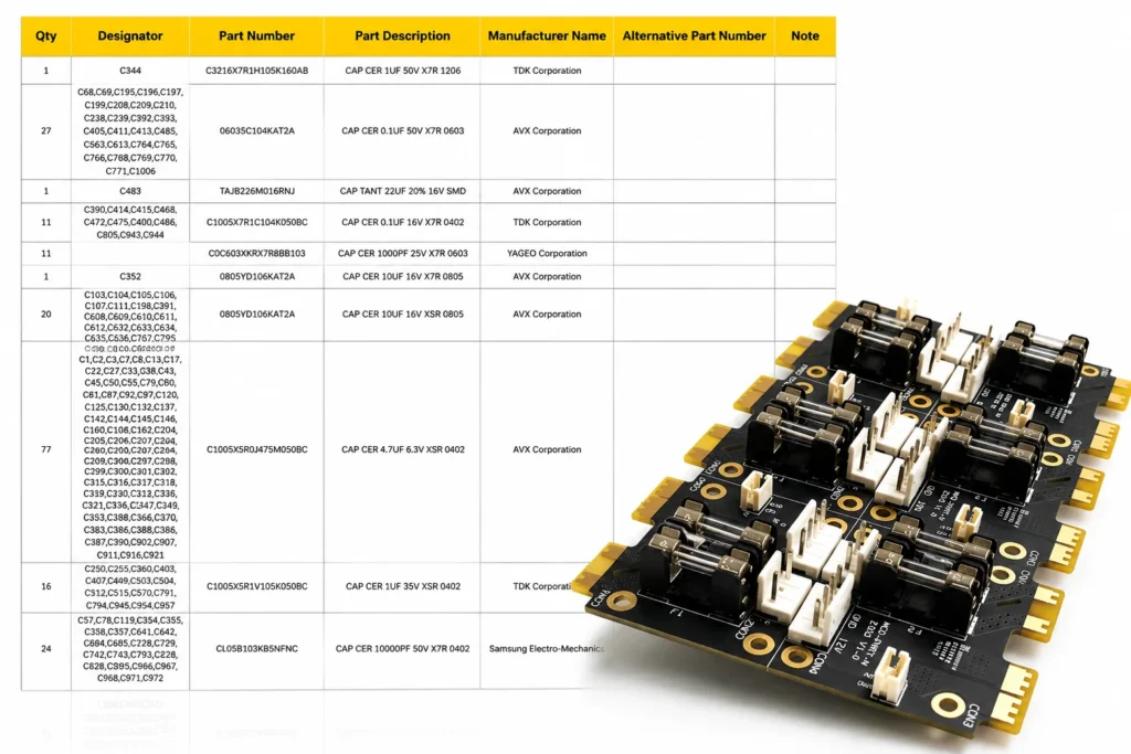
For SMT assembly, common DFM checks include:
- Pad design and solder mask openings
- Component spacing and placement direction
- BGA and fine-pitch package requirements
- Fiducial placement for automated machines
- Thermal design for power components
For THT assembly, engineers usually focus on:
- Hole size and lead diameter matching
- Annular ring requirements
- Component height and mechanical clearance
- Wave soldering accessibility
- Selective soldering areas
A complete DFM review also checks BOM information, polarity markings, missing values, unavailable components, and possible alternative parts.
Early DFM feedback can reduce assembly delays, improve yield, and prevent costly redesigns after production begins.
Conclusion
SMT suits compact, high-density products and automated production. Its short connections also support high-speed electrical performance.
THT remains valuable for connectors, switches, large power parts, and other components exposed to mechanical stress. It also supports convenient manual assembly and repair.
Many products gain the best result from mixed assembly. You can use SMT for most electronic functions and THT for selected mechanical or power components.
The right decision should account for component type, production volume, board size, reliability, inspection, and total cost.
FAQ