QR Code PCB Guide: Design, Marking, Size, and Traceability
 steve ran
August 17, 2026
steve ran
August 17, 2026
A QR code PCB has a machine-readable code printed, etched, labeled, or laser-marked on the board. The code can identify a product, link to technical documents, or connect each physical board to its manufacturing and test records.
This guide explains how to design, manufacture, serialize, and verify QR codes on printed circuit boards. It also compares QR codes with Data Matrix codes and provides practical guidance for engineering and procurement teams.
What Is a QR Code PCB?
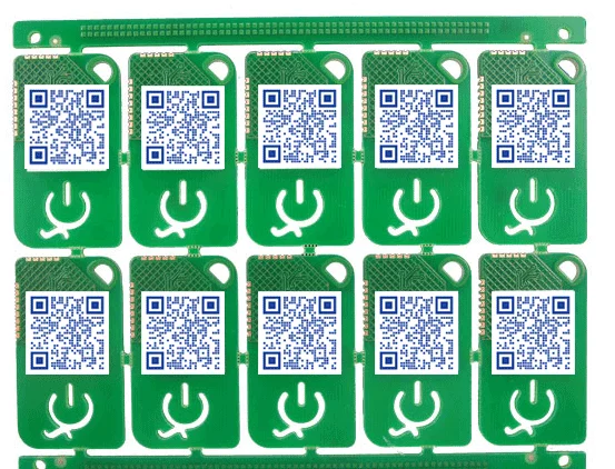
The term “QR code PCB” usually describes a circuit board with a QR code on its surface.
The code may be part of the original PCB design or added later during fabrication, assembly, or final product labeling. Some codes remain the same across every board. Others contain a unique serial number for each unit.
Common data stored in or connected to a PCB QR code includes:
- PCB part number and revision
- Manufacturing lot or date code
- Unique board serial number
- Test record identifier
- Warranty or service record
- Product documentation URL
- Firmware download page
- Installation instructions
A short identifier often works better than a large block of embedded data. The identifier can point to a database where authorized users access current production, testing, and service information.
Static and serialized QR codes
A static QR code contains the same information on every board. For example, it may open a product manual or identify the PCB model and revision. Designers can place this type directly in a silkscreen, solder mask, or copper Gerber layer.
A serialized QR code changes from one board to the next. Each code may represent a unique serial number linked to material records, assembly history, test results, and shipment data. The manufacturer usually generates and applies these codes during production.
| Marking Method | Variable Data | Durability | Main Advantage | Main Limitation |
|---|---|---|---|---|
| Silkscreen | Usually no | Moderate | Included in standard PCB artwork | Limited resolution |
| Copper and solder mask | Usually no | High | Integrated into the PCB structure | Requires careful DFM |
| Laser marking | Yes | High when qualified | Permanent serialization | Requires controlled equipment |
| Printed label | Yes | Depends on material | Flexible and high contrast | Adhesive and process compatibility |
Before selecting a marking method, define whether the project needs product identification or unit-level traceability. That decision affects the inspection process, cost, and lead time.
Why Add a QR Code to a PCB?
QR codes give manufacturers a compact way to connect a physical board with digital information. This connection can continue from bare-board fabrication through assembly, and field service.
Manufacturing traceability
A unique code can connect a board to its fabrication lot, material batch, production date, inspection results, and process history. During PCBA production, the same identifier can link the bare board to solder paste inspection, placement, AOI, X-ray, in-circuit test, and functional test records.
The code does not store all this information by itself. In most systems, it stores a short identifier that points to records in an MES, or service platform.
Inventory and production control
Operators can scan a PCB at each manufacturing stage instead of entering part numbers manually. Scanning can reduce identification errors and confirm that the correct product, program, and process route are in use.
For example, a mixed production line may assemble several revisions of the same controller. A scan before SMT placement can identify the revision and call the correct machine program. A second scan before testing can load the matching test limits.
Field Service, Documentation, and Serial Number Lookup
A customer-facing QR code may open an installation guide, support page, schematic reference, or firmware download page. This approach works well when technicians or end users need access through a standard smartphone.
For serialized products, a circuit board serial number lookup page can provide information about a specific unit. The page may show the PCB model, hardware revision, production date, warranty status, or service history.
A stable redirect URL is usually safer than placing a final document address directly in the QR code. The product team can update the destination later without changing the physical marking. Sensitive manufacturing and customer data should remain behind suitable access controls.
Warranty and product identification
A serialized code can connect a returned product to its production and test history. Service teams can confirm the model, revision, production date, and warranty status without relying only on packaging or removable labels.
However, a standard QR code offers limited anti-counterfeit protection because another party can copy the image. Stronger protection requires controlled serial numbers, authenticated database responses, signed data, tamper-evident features, or another security layer.
QR Code vs Data Matrix for PCB Marking
QR Code and Data Matrix are both two-dimensional machine-readable symbols. Their best applications often differ.
QR codes have three large position markers in their corners. Most modern smartphones can recognize QR codes without a dedicated app. This makes them useful for product documentation and customer-facing links.
Data Matrix codes use an L-shaped finder pattern. They can represent data in a compact area and are common in industrial identification and direct-part marking. Industrial scanners often support both formats.
| Factor | QR Code | Data Matrix |
| Smartphone access | Broad support | Support depends on device or application |
| Space efficiency | Requires more area for comparable short data | Often suits smaller marking areas |
| Common PCB use | URLs, documentation, general identification | Unit serialization and industrial tracking |
| Visual structure | Three corner position markers | L-shaped finder pattern |
| Scanner requirement | Smartphone or industrial scanner | Industrial scanner commonly used |
| Data management | Static or serialized | Often serialized |
Choose a QR code when technicians or customers need to scan the board with a phone. Consider Data Matrix when the available marking area is small and the code serves an internal production system.
PCB QR Code Marking Methods
Manufacturers can apply a QR code in several ways. Each method offers a different balance of cost, durability, resolution, contrast, and serialization support.
Silkscreen QR code
A silkscreen QR code is part of the PCB legend. White legend ink on green, blue, red, or black solder mask can create useful contrast when the printed modules are large enough for the process.
Silkscreen works well for fixed information such as a product page, board family, or revision identifier. A standard Gerber legend normally produces the same code on every board.
The main limitation comes from print resolution and registration. Small spaces may close, narrow modules may spread, and nearby pads may cause the manufacturer’s CAM system to clip the silkscreen. You should confirm the minimum legend line width and spacing with the PCB fabricator.
Copper and solder mask QR code
You can create a code through controlled copper and solder mask geometry. Exposed copper with a surface finish may form one part of the pattern, while solder mask forms the contrasting background.
This approach can produce a durable board-integrated mark, but the design requires more attention than a silkscreen code. The engineer must consider copper clearance, solder mask registration, surface finish, oxidation protection, electrical function, and reflected light.
A decorative copper QR code should remain electrically isolated or connect only as intentionally designed. Designers should not allow the marking to create unintended conductive paths, antennas, or clearance violations.
Laser-marked QR code
Laser marking can create a permanent code on a solder mask or other qualified board surface. It also supports variable data, making it suitable for individual serial numbers.
The laser process must match the board material and surface. Excessive energy may damage the solder mask, expose copper, or leave residue. The manufacturer should establish a controlled process and approve the result through samples.
Laser marking often fits automated traceability systems. A production line can create a serial number, mark the board, scan the result, and link the ID to records.
Printed label
A printed label offers flexible data and strong contrast. It can carry a QR code, Data Matrix, readable serial number, and other markings in one area.
Label material and adhesive must suit the point at which the label enters production. A label applied before reflow may need to tolerate heat, flux, cleaning agents, and handling. A label applied after assembly avoids some of these stresses but cannot identify the bare PCB during earlier processes.
Labels may become damaged over time. Product environment and service life should guide the material choice.
| Marking Method | Variable Data | Durability | Main Advantage | Main Limitation |
| Silkscreen | Usually no | Moderate | Included in standard PCB artwork | Limited resolution |
| Copper and solder mask | Usually no | High | Integrated into the PCB structure | Requires careful DFM |
| Laser marking | Yes | High when qualified | Permanent serialization | Requires controlled equipment |
| Printed label | Yes | Depends on material | Flexible and high contrast | Adhesive and process compatibility |
No method works for every project. A fixed documentation link may need only silkscreen. A medical, automotive, or industrial assembly may require permanent serialization, process records, and verified machine scanning.
Need a PCB with QR code marking or serialized traceability?
Send your design files and marking requirements to HXD Circuit for a practical DFM review and quotation.
Get StartedKey Design Rules for a Scannable PCB QR Code
A successful code begins with the data rather than the physical graphic. More characters can require a denser symbol, which either increases the overall dimensions or reduces the size of each module.
Keep the encoded data short
A short serial number or redirect URL usually produces a simpler code than a long product description. Simpler codes give the manufacturer more room to reproduce each module clearly.
Avoid placing confidential production information directly in a code that anyone can scan. Use an opaque identifier and control access through the connected database or web application when security matters.
Match module size to the manufacturing process
A module is one square element within a QR code. Its physical size determines how well the marking process can reproduce the pattern.
No universal minimum PCB QR code size applies to every factory or method. Silkscreen resolution, solder mask alignment, laser spot size, board color, surface texture, scanner optics, and encoded data affect results.
PCB designers should use generic online size tips as a starting point. Then confirm the design with the fabricator and test real samples.
Preserve the quiet zone
A QR code requires a blank margin around the symbol. The standard QR Code quiet zone extends four modules on every side.
Copper features, text, vias, pads, component outlines, and board edges must stay out of this area.
They should not enter if it reduces visual separation. The blank border allows the scanner to identify the symbol boundary.
For example, if one module measures 0.30 mm, the quiet zone would require 1.20 mm on each side. This example shows the calculation only; it does not define a universal PCB module size.
Maintain strong contrast
The scanner must distinguish light modules from dark modules. White silkscreen on a dark solder mask often provides clear contrast, but ink coverage and mask color still affect the result.
Exposed metal can reflect inspection lights and phone flashes. A code may appear clear from one angle but lose contrast from another. Sample testing should include realistic lighting, distance, and viewing angles.
Select error correction carefully
QR codes provide several error correction levels. Higher correction can recover from more local damage, but it also increases symbol density for the same encoded data.
A clean code inside an enclosure may not need the same correction level as a code exposed to dirt, abrasion, or coating. Select the level according to the application, available board area, and scanning tests.
Use vector or native EDA objects
Native QR code tools in PCB design software provide more predictable geometry than a low-resolution screenshot. Vector files can also work when the import process preserves scale and module shape.
Avoid blurred raster images, anti-aliased edges, rounded modules, gradients, or decorative changes. The Gerber or ODB++ output should contain clear square geometry.
How to Add a QR Code in PCB Design Software
Modern PCB design tools can create barcodes directly or import vector artwork.
Adding a QR code in KiCad
Current KiCad PCB Editor documentation describes a barcode tool that supports QR Code and other barcode types. Designers can enter the encoded text, select the symbol type, configure available properties, and place the result on a PCB layer.
After placement, check the physical dimensions and quiet zone. Then open the generated fabrication files in a Gerber viewer. Confirm that every module remains square and that no layer-processing rule clips the code.
Software features can change between versions, so use the documentation that matches the installed KiCad release.
Importing SVG or DXF artwork
An imported vector may work when the PCB tool does not offer a native barcode function. Generate the code with square modules, include the required quiet zone, and remove unsupported effects.
After import, confirm the dimensions. Unit conversion between pixels, millimeters, inches, and drawing units can change the intended scale. Run a design-rule check and inspect the exported manufacturing data.
Conclusion
A QR code can connect a PCB to documentation, production records, testing data, inventory systems, and field service information. Data Matrix may offer a better fit when industrial serialization must fit into a smaller area. You must control encoded data, module size, and scanning conditions.
FAQ