SMD vs. SMT: What’s the Difference in PCB Assembly?
 steve ran
September 6, 2026
steve ran
September 6, 2026
SMD and SMT are related but different terms in PCB assembly. SMD (Surface-Mount Device) is a part mounted on a PCB surface. SMT (Surface-Mount Technology) is the process used to place and solder SMDs.
They are not competing assembly options. Understanding the difference helps with PCB design, BOM preparation, and communication with assembly suppliers.
What Is an SMD?
An SMD is a component mounted directly on PCB surface pads without using through-holes.
SMD describes how a component mounts to the PCB, not its electrical function. Resistors, capacitors, diodes, transistors, LEDs, connectors, and ICs can all be SMDs.
SMDs have different terminal structures, including metal end caps, leads, bottom contacts, and solder balls. These structures affect PCB pad design, component placement, soldering, and inspection.
Common Types of SMD Components
Common SMD components include:
- Chip resistors: Control current, divide voltage, or provide circuit termination.
- Multilayer ceramic capacitors: Provide filtering, decoupling, and energy storage.
- SMD inductors: Support filtering, power conversion, and signal-processing circuits.
- Diodes and transistors: Perform switching, rectification, protection, or amplification.
- SOIC and QFP packages: Integrated-circuit packages with visible leads around two or four sides.
- QFN and DFN packages: Leadless packages with terminals under or near the package edges.
- BGA packages: Integrated circuits that use an array of solder balls under the package.
- Surface-mount connectors and LEDs: Components designed for direct attachment to PCB surface pads.
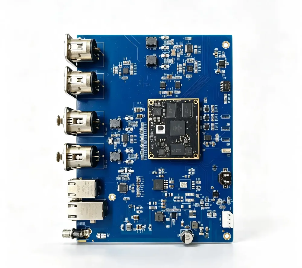
Different SMD packages require different assembly and inspection methods. Package size, terminal type, thermal behavior, polarity, and supply format can all affect the process.
For example, AOI can inspect the visible leads of SOIC and QFP packages. Manufacturers may use X-ray inspection to check the hidden solder joints under BGA packages.
IPC-A-610 covers acceptance criteria for several surface-mount component and solder-joint categories, including leaded and leadless packages.
What Is SMT?
Surface-Mount Technology (SMT) is the process used to mount and solder components onto PCB surface pads. It includes materials, equipment, production data, process control, inspection, and quality checks.
SMT is not a single machine or production step. Pick-and-place and reflow soldering are both parts of the SMT process.
A typical SMT workflow may include:
- Reviewing PCB and assembly data
- Preparing components and solder paste
- Printing solder paste
- Inspecting the solder paste when required
- Placing SMDs
- Reflow soldering
- Inspecting the assembled board
- Performing specified electrical tests
The exact workflow depends on the PCB design, component packages, production volume, and agreed quality requirements.
Main Differences Between SMD and SMT
| Point of comparison | SMD | SMT |
| Describes | A physical component | An assembly technology |
| Examples | Chip resistor, QFN, BGA, SMD LED | Paste printing, placement, reflow |
| Appears mainly in | BOMs, component datasheets and approved part lists | Work instructions and process-control documents |
| Key information | Part number, package, dimensions and ratings | Equipment, materials, profiles and inspection |
An SMD has specifications such as a part number, package type, electrical ratings, dimensions, and polarity. Engineers use this information to select the component and design the correct PCB footprint.
SMT describes how the SMD is assembled onto the PCB, including solder paste printing, component placement, soldering, and process control.
They Appear in Different Manufacturing Documents
SMD and SMT information appears in different production files.
The BOM lists the required components, including part numbers, quantities, reference designators, and approved alternatives.
The pick-and-place file provides component locations, rotations, and board sides for placement.
The assembly drawing shows polarity, orientation, and other assembly instructions.
Gerber and drill files mainly define PCB fabrication data. Formats like ODB++ can include more assembly details. You must confirm the required files with the PCB assembler before production.
How Do SMD and SMT Work Together?
Consider a chip resistor in a PCB assembly:
- The BOM identifies the resistor and part number.
- PCB data defines its footprint and pads.
- A stencil prints solder paste onto the pads.
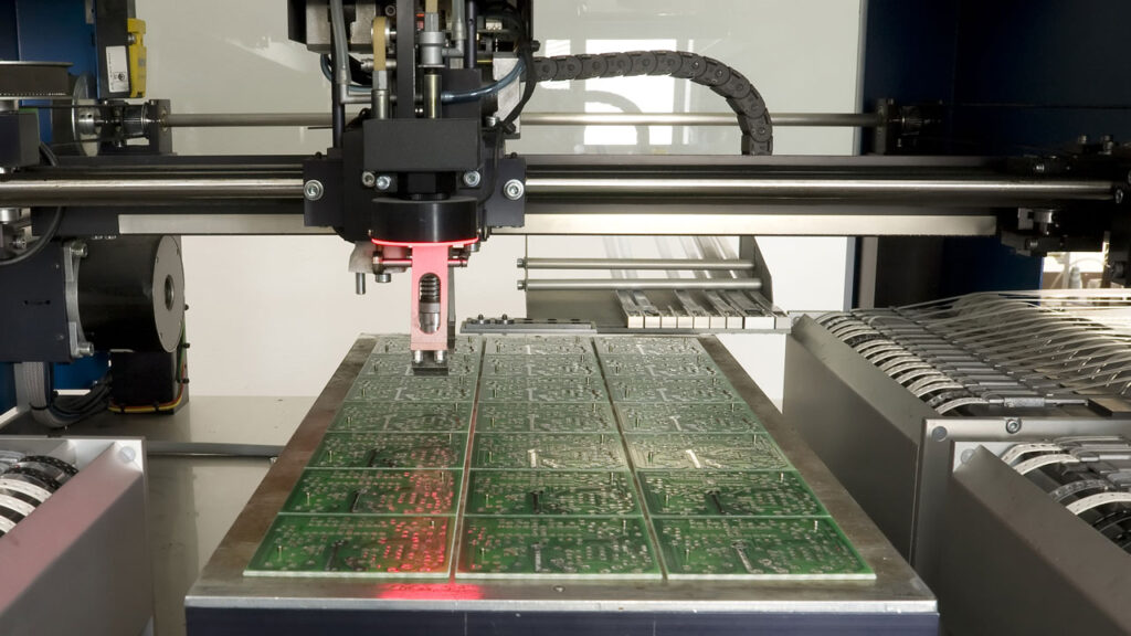
- A pick-and-place machine positions the resistor.
- Reflow soldering melts the solder and forms the joints.
- Inspection checks the component position and solder joints.
The resistor is the SMD. Printing, placement, reflow, and inspection are parts of the SMT process.
This is why SMD and SMT should not be compared as two assembly options. SMD refers to the component, while SMT refers to the process used to assemble it.
SMD, SMT, and Through-Hole: What Is the Difference?
SMD, SMT, and through-hole are not three equivalent terms. Through-hole can refer to either a leaded component or Through-Hole Technology (THT).
| Term | What it describes | Basic use |
| SMD | A surface-mount component | Mounted on PCB surface pads |
| SMT | A surface-mount assembly technology | Places and solders SMDs |
| Through-hole component | A component with leads that enter PCB holes | Installed through drilled holes |
| THT | Through-hole assembly technology | Installs and solders through-hole components |
SMD vs. Through-Hole Components
The correct comparison is SMD versus through-hole components.
SMD terminals connect to pads on the PCB surface, while through-hole leads pass through drilled holes.
SMDs are well suited for compact designs and automated assembly. Through-hole components are often used for connectors, large parts, or components that need stronger mechanical support.
SMT vs. Through-Hole Technology
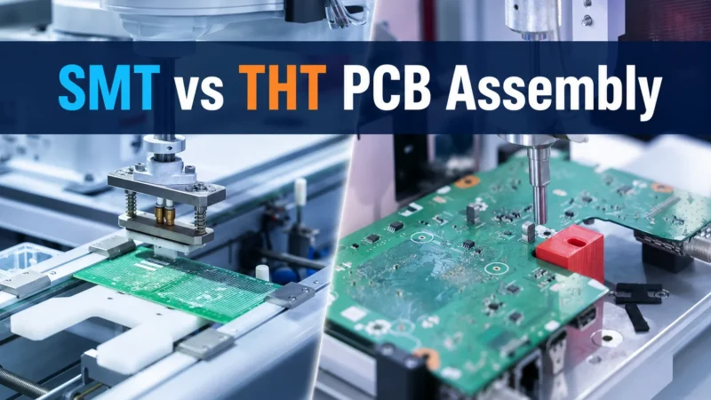
SMT typically uses solder paste printing, automated placement, and reflow soldering. THT inserts component leads through PCB holes and may use wave, selective, or manual soldering.
SMT is ideal for high-density and automated assembly. Designers often use THT for connectors, transformers, switches, and other components better suited to through-hole mounting.
A PCBA can include both SMD and through-hole components. This is called a mixed-technology assembly.
The process may combine reflow with wave, selective, or hand soldering, depending on the PCB design and component requirements.
Designers should plan mixed assembly early because through-hole parts can affect spacing, tooling, inspection, and production cost.
What Does the SMT Assembly Process Include?
A typical SMT assembly process includes solder paste printing, component placement, reflow soldering, and inspection.
Solder Paste Printing
A stencil applies solder paste to selected PCB pads. Stencil design, paste properties, and printer settings affect the amount and position of the paste.
Poor paste deposits can cause opens, bridges, insufficient solder, and other defects. Solder Paste Inspection (SPI) can check the paste before component placement when required.
SMD Component Placement
Pick-and-place machines collect components from reels, trays, tubes, or other packaging and place them at programmed positions on the PCB.
Package size and type affect feeder, nozzle, vision, and placement settings. The machine also needs correct rotation, polarity, and Pin 1 data.
Note that SOIC, QFN, and BGA denote component package types, while tape-and-reel, tray, and tube describe how suppliers provide components.
Reflow Soldering
After placement, the PCB passes through a controlled reflow profile. Heat melts the solder paste. This lets it form electrical and mechanical connections between the SMD terminals and PCB pads.
Some moisture-sensitive SMDs also require special handling before reflow. J-STD-020F covers moisture/reflow sensitivity classification, while J-STD-033D covers the handling of moisture- and process-sensitive devices.
Inspection and Testing
After reflow, manufacturers may use visual inspection, AOI, X-ray, electrical testing, or a combination of these methods.
AOI checks component position, orientation, and visible solder joints. X-ray is useful for hidden joints under packages such as BGAs. Electrical testing checks circuit performance that visual inspection alone cannot confirm.
The inspection method depends on the component package, product requirements, and quality plan.
Conclusion
SMD stands for Surface-Mount Device, while SMT stands for Surface-Mount Technology. Simply put, SMD is the component, and SMT is the process used to assemble it.
HXD Circuit can review PCB and assembly files before production and identify missing component, or manufacturing information.
FAQ
1. Is a resistor an SMD or an SMT component?
A surface-mount resistor is an SMD. “SMT component” is commonly used, but SMD is more precise because SMT refers to the assembly process.
2. Is BGA an SMD?
Yes. BGA is a surface-mount package that connects to PCB pads through solder balls under the component. Because the joints are hidden, X-ray inspection may be used.
3. Can SMD components be soldered by hand?
Yes. Many SMDs can be hand-soldered. The difficulty depends on package size, terminal access, PCB layout, tools, and operator skill. Small or leadless packages may require hot air or reflow equipment.
4. Does SMT only mean reflow soldering?
No. Reflow is only one part of SMT. The process can also include solder paste printing, component placement, inspection, and process control.
5. Can one PCB contain both SMD and through-hole components?
Yes. This is called mixed-technology assembly. The PCB may use reflow for SMDs and wave, selective, or hand soldering for through-hole components.
6. What does SMD mean in BGA pad design?
In BGA pad design, SMD can mean solder-mask-defined rather than Surface-Mount Device. The solder mask opening defines the exposed soldering area of the pad. TI application report
7. What files are needed for SMT assembly?
Common files include PCB manufacturing data, a BOM, pick-and-place data, and an assembly drawing. Polarity, test, and other product-specific requirements should also be provided.
8. Is “SMD PCB” technically correct?
“SMD PCB” is commonly understood but not precise. A clearer term is “PCB designed for SMDs” or “PCBA with SMDs,” depending on the context.